
Display device, electronic apparatus and illumination device

Active Publication Date: 2013-01-17
138 EAST LCD ADVANCEMENTS LTD
View PDF10 Cites 44 Cited by
  • Summary
  • Abstract
  • Description
  • Claims
  • Application Information

AI Technical Summary

Benefits of technology

The invention provides a display device with a frame that helps release heat from the light-emitting elements, regardless of whether the frame surrounds the elements and the light guide plate. This allows for efficient heat dissipation, which is beneficial for electronic devices that use the display device. The technical effect of this invention is that it helps improve the performance and reliability of display devices used in electronic devices.

Problems solved by technology

In the illumination device having such a configuration, as the temperature of the light-emitting elements increases, the light-emitting elements have problems such as a decrease of light-emitting efficiency, ununiform brightness, and short product life.
However, the use of a frame has a problem that dissipation of heat from the light-emitting elements is lowered, in spite of the fact that dissipation of heat from the light-emitting elements is important in the illumination device.

Method used


Image

  • Display device, electronic apparatus and illumination device
  • Display device, electronic apparatus and illumination device
  • Display device, electronic apparatus and illumination device

Examples


embodiment 1

Overall Configuration

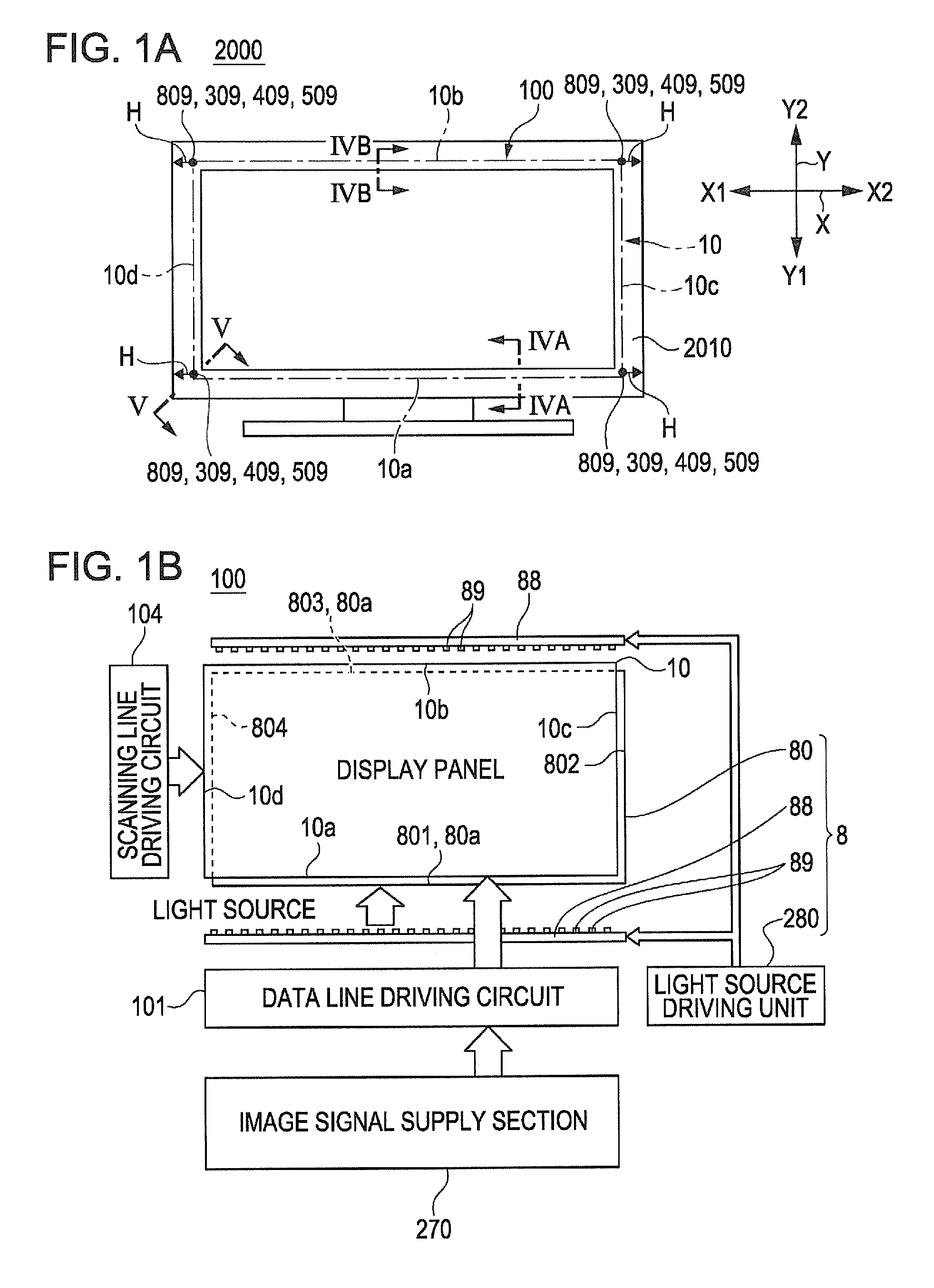
[0041]FIGS. 1A and 1B are explanatory views of a liquid crystal television set (electronic apparatus) having a display device according to an embodiment 1 of the invention. FIG. 1A is an explanatory view which schematically shows the appearance of the liquid crystal television set, and FIG. 1B is a block diagram which shows electric configuration of the display device.

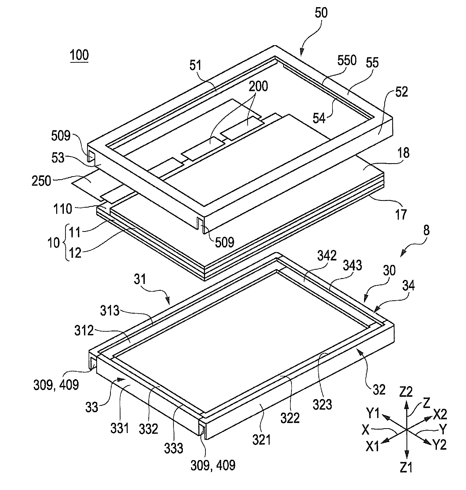
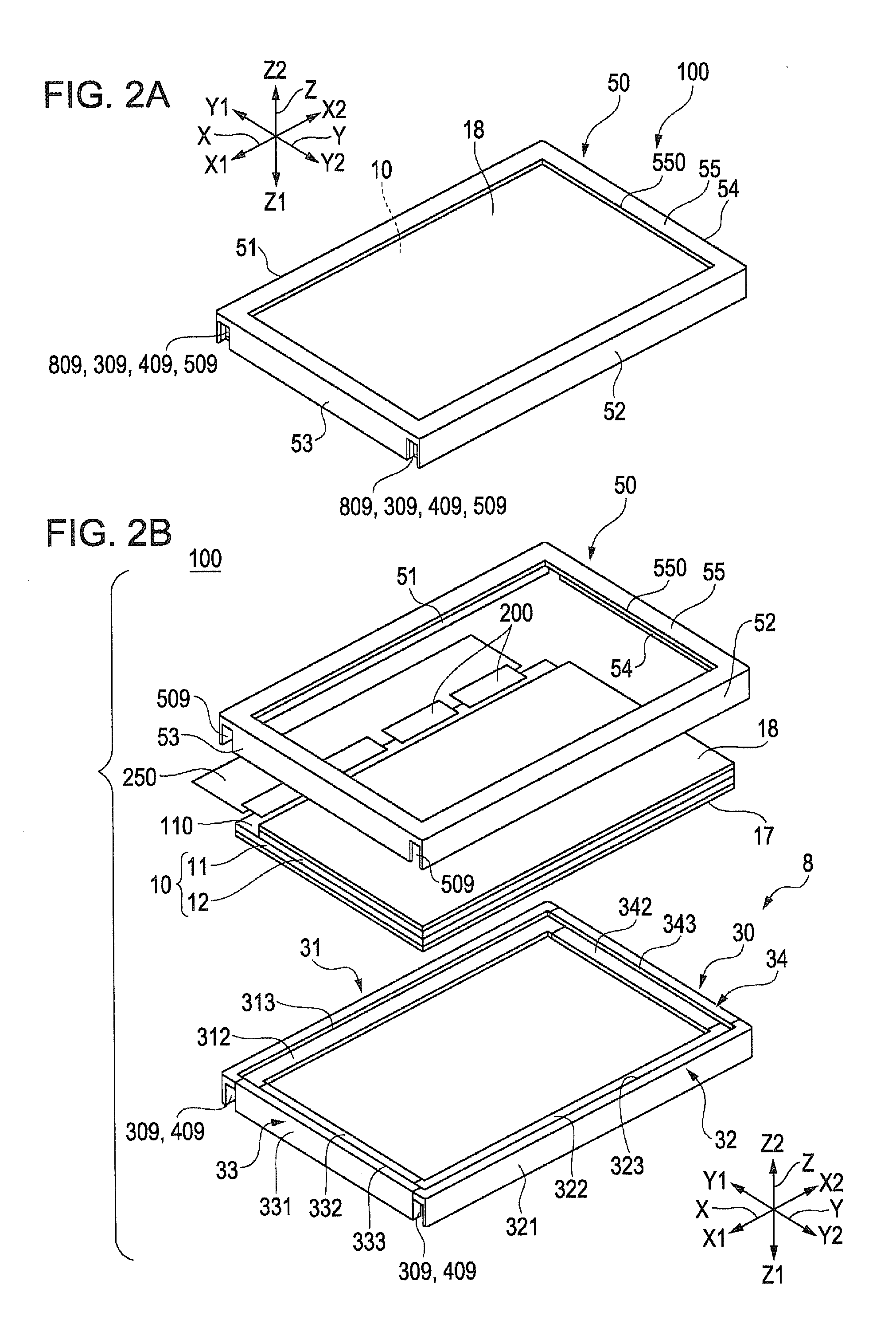
[0042]An electronic apparatus 2000 shown in FIG. 1A is a liquid crystal television set and includes a display device 100 and a frame 2010 for the television set. As shown in FIG. 1B, the display device 100 includes a display panel 10 (liquid crystal panel), which will be described later in detail with reference to the drawings such as FIGS. 2A and 2B, an image signal supply section 270 that supplies image signals to the display panel 10 from the outside via a flexible wiring board and an illumination device 8 that is disposed on the backside of the display panel 10 and supplies illumination light. ...

embodiment 2

[0069]FIGS. 7A and 7B are explanatory views which show an illumination device 8 of a display device 100 according to an embodiment 2 of the invention. FIG. 7A is an explanatory view which shows positioning of penetrating sections 809 in the display device 100, and FIG. 7B is a sectional view around the penetrating section 809 in the display device 100 taken along the line VIIB-VIIB of FIG. 7A. FIG. 8 is an exploded perspective view which shows further details of the display device according to the embodiment 2. The essential configuration of the embodiment 2 is the same as that of the embodiment 1, therefore the same numbers are used for the same elements so as to omit their explanation.

[0070]In the embodiment 1, in each closed space 8a formed on each side of the Y axis direction (the side on which a plurality of light-emitting elements 89 are mounted), each opening is formed on each side plate of the frame that intersects the extending direction (extended line) of the closed space ...

embodiment 3

[0072]FIG. 10 is an explanatory view which shows penetrating sections 809 formed in an illumination device 8 of a display device 100 according to an embodiment 3 of the invention. The essential configuration of the embodiment 3 is the same as that of the embodiment 1, therefore the same numbers are used for the same elements so as to omit their explanation.

[0073]In the embodiment 2, in the closed spaces 8a formed on both sides of the Y axis direction, the penetrating section 809 is formed on each end of the closed spaces 8a, although the opening direction of the penetrating section 809 differs from that of the embodiment 1.

[0074]In the embodiment 3 as shown in FIG. 10, in the closed space 8a formed on the other side Y2 of the Y axis direction, which is one of the two closed spaces 8a formed on both sides of the Y axis direction, the penetrating sections 809 are formed at positions between both ends of the closed space 8a in the extending direction of the closed space 8a. As describe...


PUM


Abstract

An illumination device of a display device is configured such that heat of light-emitting elements is dissipated via a light source substrate, a light source support member made of a metal, and a first frame made of a metal. The illumination device also includes a second frame made of a resin that is disposed such that a closed space is formed along the light source support member between the frame and the light source support member. The second frame has an opening portion that communicates with the closed space, and the first frame and a third frame each has an opening portion at a position that overlaps the opening portion of the second frame, thereby allowing heat of the light-emitting elements to be dissipated through the closed space and an opening which is formed by opening portions.

Description

BACKGROUND[0001]1. Technical Field[0002]The present invention relates to a display device having an illumination device and a display panel, an electronic apparatus having a display device, and the illumination device.[0003]2. Related Art[0004]A liquid crystal device, which is one of the various display devices, includes an illumination device which is called a backlight unit, and a transmissive type or semi-transmissive type display panel (liquid crystal panel) that is disposed on a light exiting surface of the illumination device. In the illumination device, a plurality of light-emitting elements are arranged along the side end face of the light guide plate which serves as a light incident portion, as described in JP-A-2002-229022, JP-A-2009-3081 and JP-A-2011-40388.[0005]In the illumination device having such a configuration, as the temperature of the light-emitting elements increases, the light-emitting elements have problems such as a decrease of light-emitting efficiency, unun...

Claims


Application Information

Patent Timeline
IPC IPC(8): F21V8/00
CPCG02F1/133308G02F1/133615G02B6/009G02B6/0085G02F2001/133628G02F1/133628
Inventor MOMOSE, YOICHIURANO, NOBUTAKA
Owner 138 EAST LCD ADVANCEMENTS LTD
Features
  • Generate Ideas
  • Intellectual Property
  • Life Sciences
  • Materials
  • Tech Scout
  • Unparalleled Data Quality
  • Higher Quality Content
  • 60% Fewer Hallucinations
Learn More