Shift register

a technology of shift register and shift register, applied in the field of shift register, can solve the problems of poor picture quality, poor picture quality, set node to float, etc., and achieve the effect of preventing a picture quality from becoming poor and ensuring drive stability

Active Publication Date: 2013-01-17
LG DISPLAY CO LTD
View PDF0 Cites 20 Cited by
  • Summary
  • Abstract
  • Description
  • Claims
  • Application Information

AI Technical Summary

Benefits of technology

[0012]An object of the present invention is to provide a shift register in which a pull-up switching device is turned off positively in a period in which no scan pulse is forwarded for securing drive stability and prevents a picture quality from becoming poor.

Problems solved by technology

In the meantime, if the pull up TFT is turned on in the period in which no scan pulse is forwarded, an output voltage of a stage which is required to sustain the low voltage becomes unstable, which is likely to cause a poor picture quality.
The shift register has a problem in that many control TFTS do not operate in the blank period, causing the set node to float.
Once the set node is floated, a leakage current is liable to generate in the pull up TFT due to coupling, and the output voltage of the stage becomes unstable, resulting in a poor picture quality.

Method used


Image

  • Shift register
  • Shift register
  • Shift register

Examples


first embodiment

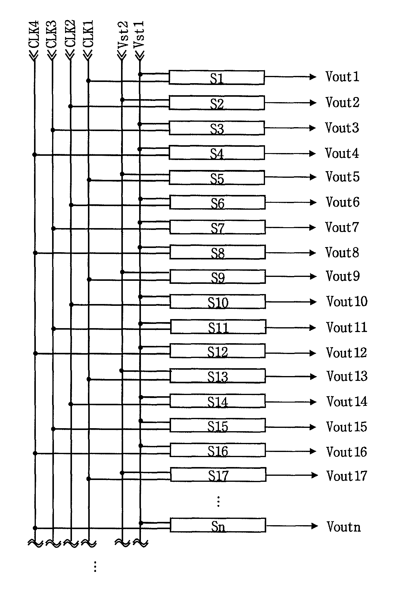
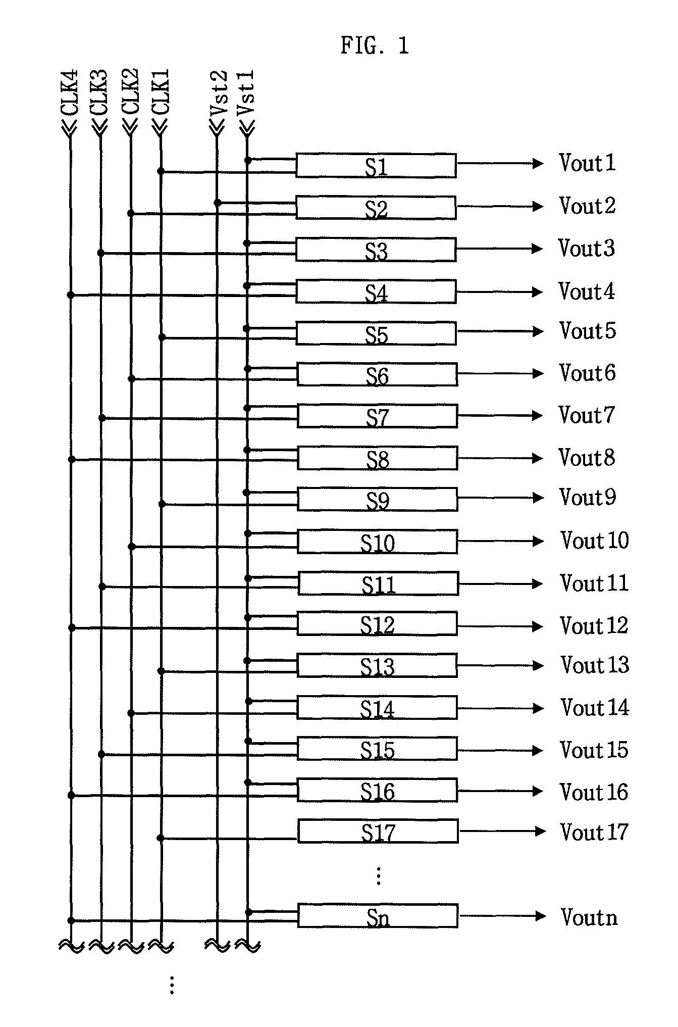
[0068]The first to fourth clock pulses CLK1˜CLK4 cycles repetitively with phases different from one another. Each of the clock pulses CLK1˜CLK4 is in a high state for two horizontal periods. And, the first to fourth clock pulses CLK1˜CLK4 are forwarded with one horizontal period delay to one another (adjacent two clock pulses are overlapped for one horizontal period). In the meantime, though the clock pulses CLK1 CLK4 in the first embodiment include four kinds of clock pulses having phases different from one another, a number of the clocks are not limited as far as the number is more than two.

[0069]The first and second start pulses Vst1 and Vst2 are forwarded with phases different from each other, with only one time of a high state at starting of every frame. The first and second start pulses Vst1 and Vst2 are at the high state for two horizontal periods, and the second start pulse Vst2 is forwarded with a delay of one horizontal period than the first start pulse Vst1. In the meanti...

third embodiment

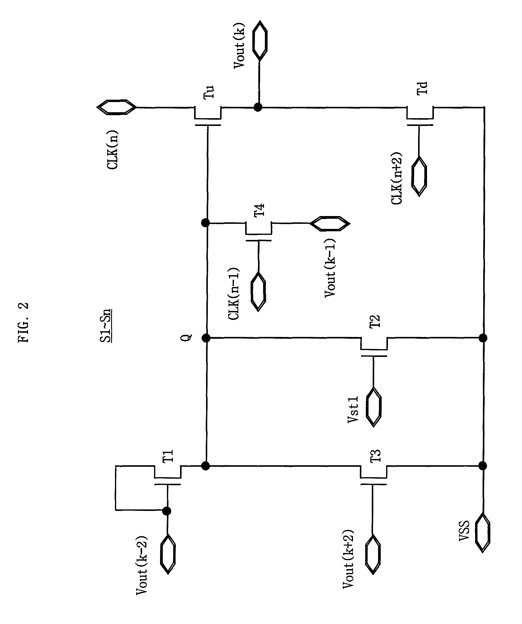
[0089]Instead, the fourth TFT T4 in the third embodiment has a gate terminal with the second start pulse Vst2 and the clock pulse delayed by three horizontal periods than the clock pulse to the pull up TFT Tu supplied thereto. According to this, the fourth TFT T4 is turned on or turned off according to the second start pulse Vst2 or the clock pulse delayed by three horizontal period than the clock pulse supplied to the pull up TFT Tu. And, the fourth TFT T4 connects the output terminal of the (k−1)th stage Sk−1 to the set node Q when the fourth TFT T4 is turned on.

[0090]Thus, the third embodiment is one in which a function of the second TFT T2 of initializing the set node Q into the low state in the F period is to be made by the fourth TFT T4. Eventually, alike the first and second embodiments, the third embodiment can prevent the unstable fluctuation of the output of the (4n+1)th stages S4n+1 in the F period from occurring. Moreover, the third embodiment has effects of cost saving ...


PUM


Abstract

A shift register is discussed in which a pull-up switching device is turned off positively in a period in which no scan pulse is forwarded for securing drive stability and prevents a picture quality from becoming poor. The shift register in one embodiment includes stages having any one of first and second start pulses, and any one of first to fourth clock pulses to forward a scan pulse in succession, wherein the first and second start pulses are in gate high voltage states for two horizontal periods, with the second start pulse forwarded with a delay of one horizontal period than the first start pulse. The first to fourth clock pulses are in gate high voltages for two horizontal periods, with one horizontal period delay to one another.

Description

CROSS REFERENCE TO RELATED APPLICATION[0001]This application claims the benefit of the Korean Patent Application No. 10-2011-0068915, filed on Jul. 12, 2011, which is hereby incorporated by reference as if fully set forth herein.BACKGROUND OF THE DISCLOSURE[0002]1. Field of the Disclosure[0003]The present invention relates to a shift register in which a pull-up switching device is turned off positively in a period in which no scan pulse is forwarded for securing drive stability and prevents a picture quality from becoming poor.[0004]2. Discussion of the Related Art[0005]Recently, a GIP (Gate In Panel) type display device is introduced, in which a gate driving circuit is built in a panel thereof for reducing volume and weight of the display device and saving production cost.[0006]In the GIP type display device, the gate driving circuit is built in a non-display region of the panel by using an amorphous silicon thin film transistor (Hereafter call as TFT). The gate driving circuit has...

Claims


Application Information

Patent Timeline
Patent Type & Authority Applications(United States)
IPC IPC(8): G11C19/00
CPCG11C19/28G09G2310/0267G11C19/00G09G2320/0233G09G2310/0286
Inventor AHN, JUNG-EUNJUNG, BO-YOUNGCHAE, JI-EUN
Owner LG DISPLAY CO LTD
Why Eureka
Try Eureka