Image forming apparatus
a technology of image forming apparatus and forming belt, which is applied in the direction of electrographic process apparatus, instruments, optics, etc., can solve the problems of color misregistration, direct influence of the increase and decrease in the speed of the driving roller, and fluctuation of the tension of the intermediary transfer belt, so as to suppress the occurrence of an image defect and suppress the fluctuation of surface speed and tension
- Summary
- Abstract
- Description
- Claims
- Application Information
AI Technical Summary
Benefits of technology
Problems solved by technology
Method used
Image

Examples
first embodiment
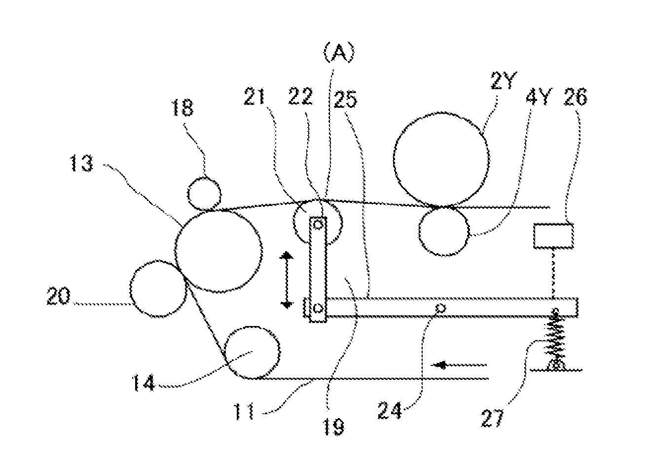
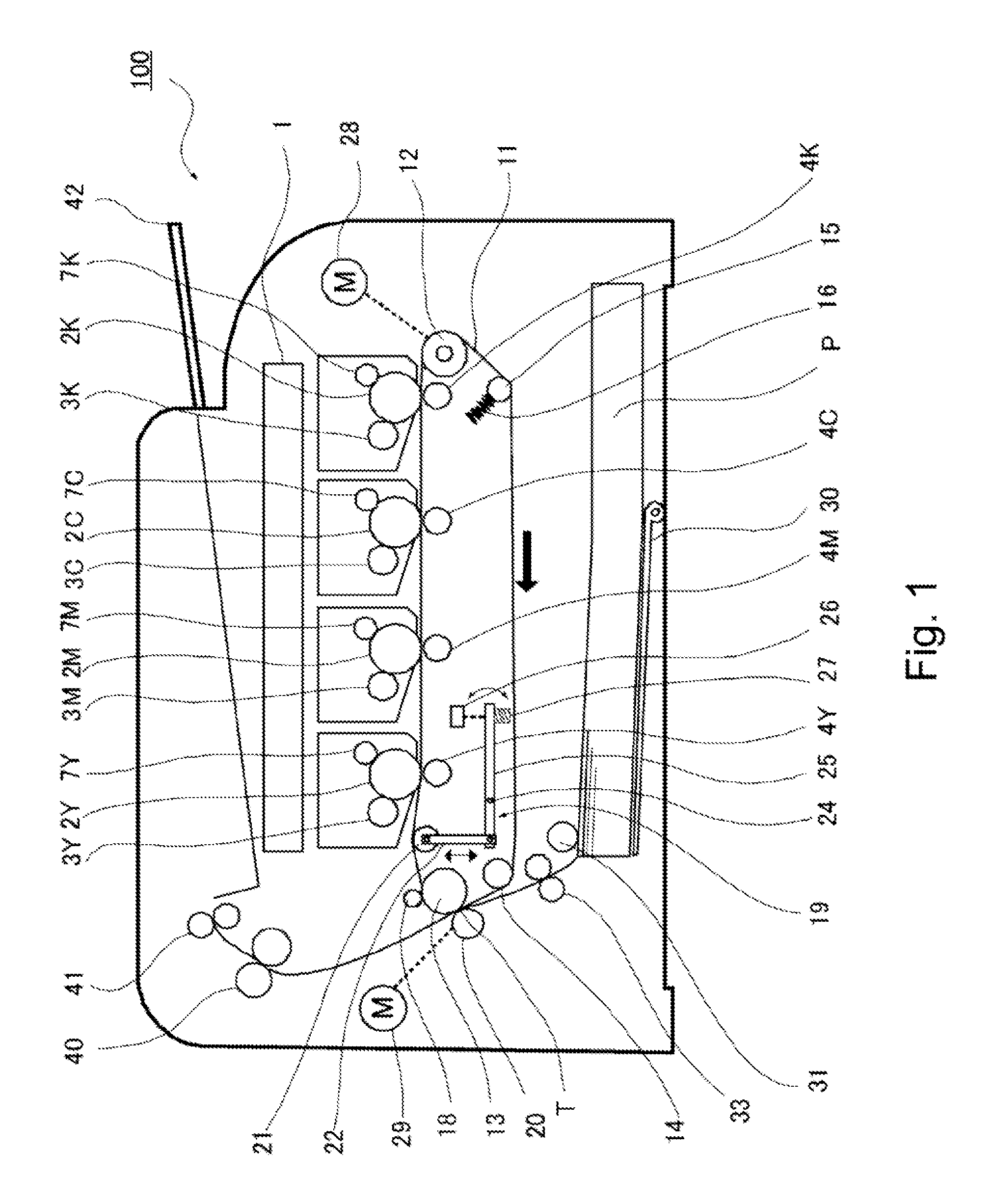
[0024]An image forming apparatus according to First Embodiment of the present invention will be described with reference to the drawings. FIG. 1 is a schematic illustration of the image forming apparatus in this embodiment. As shown in FIG. 1, in an image forming apparatus 100 in this embodiment, surfaces of photosensitive drums (image bearing members) 2Y, 2M, 2C and 2K for yellow, magenta, cyan and black, respectively are electrically charged uniformly by primary charges 7Y, 7M, 7C and 7K, respectively. The charged photosensitive drums 2Y to 2K are exposed to light depending on image information by an exposure device 1, so that electrostatic latent images are formed. The electrostatic latent images are developed with color toners into color toner images by developing devices 3Y to 3K. The respective color toner images are successively primary-transferred superposedly onto a rotatable intermediary transfer belt (endless belt) 11 by primary transfer rollers (transfer devices) 4Y to 4...
second embodiment
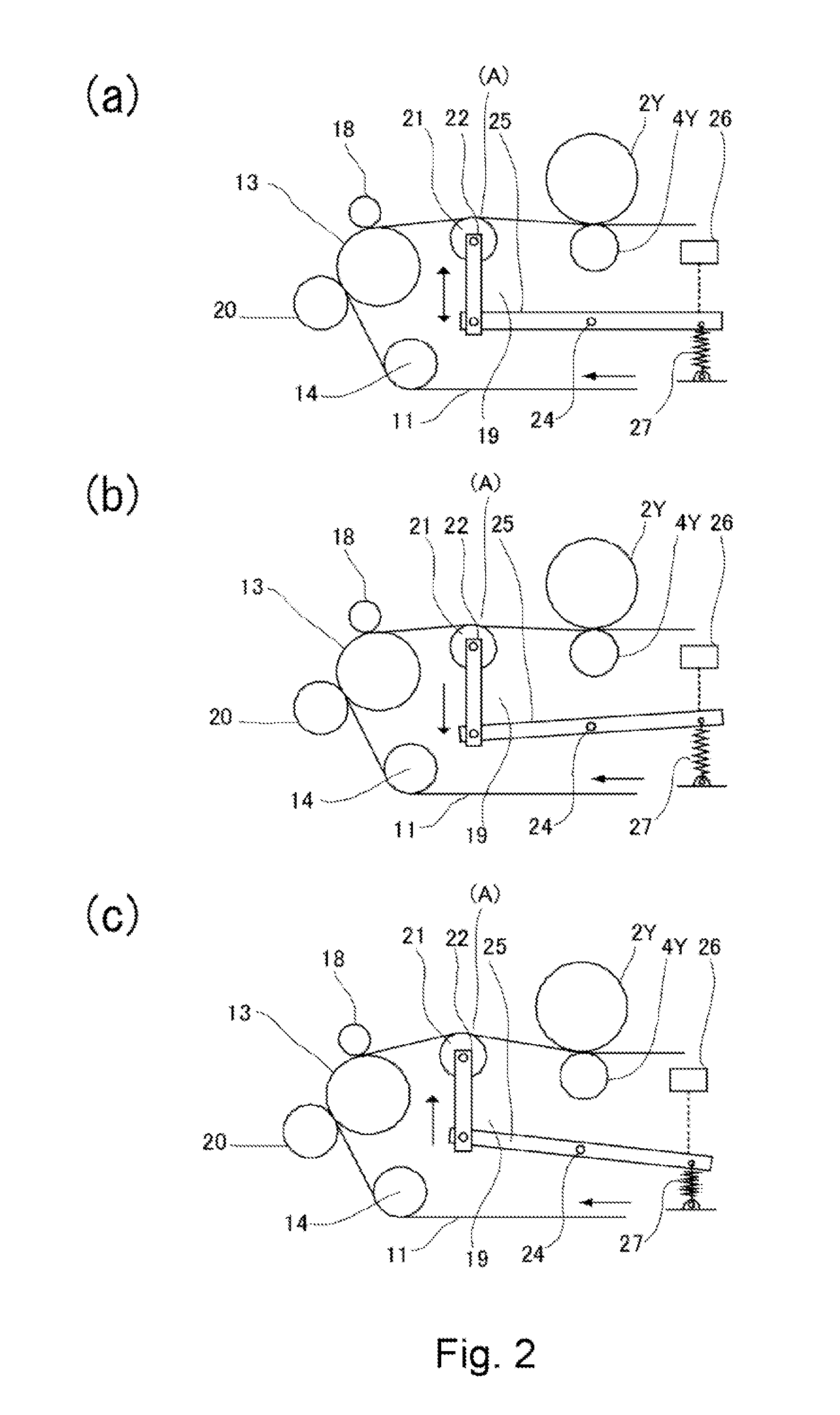
[0083]An image forming apparatus according to Second Embodiment of the present invention will be described with reference to FIG. 8. Portions similar to those in First Embodiment are represented by the same reference numerals or symbols and will be omitted from redundant description. Parts (a) to (c) of FIG. 8 are illustrations of a speed of an intermediary transfer belt in this embodiment.
[0084]As shown in (a) to (c) of FIG. 8, in the image forming apparatus in this embodiment, in place of the tension detecting unit 19 in First Embodiment, a tension detecting unit (tension detecting means) 39 is provided. The tension detecting unit 39 is constituted by a tension roller (movable device) 15, a tension spring 16 and an optical distance measuring sensor 26.
[0085]The tension roller 15 is urged against the intermediary transfer belt 11 at a position downstream of the driving roller 12 with respect to the intermediary transfer belt movement direction to apply predetermined tension to the ...
third embodiment
[0091]An image forming apparatus according to Third Embodiment of the present invention will be described with reference to FIG. 8. Portions similar to those in First Embodiment are represented by the same reference numerals or symbols and will be omitted from redundant description. Parts (a) to (c) of FIG. 9 are illustrations of a speed of an intermediary transfer belt in this embodiment.
[0092]As shown in (a) to (c) of FIG. 8, in the image forming apparatus in this embodiment, in place of the tension detecting unit 19 in First Embodiment, a tension detecting unit (tension detecting means) 59 is provided. Further, in place of the tension roller 15, a stretching roller 46 is provided. The tension detecting unit 59 includes tension detecting roller surface 61 and 62, a connecting member 43, a tension positioning member 45 and an optical (infrared) distance measuring sensor 26. Here, the tension detecting rollers 61 and 62 and the connecting member 43 constitute a movable device.
[0093]...
PUM
 Abstract
Description
Claims
Application Information
 - R&D
- Intellectual Property
- Life Sciences
- Materials
- Tech Scout
- Unparalleled Data Quality
- Higher Quality Content
- 60% Fewer Hallucinations
Browse by: Latest US Patents, China's latest patents, Technical Efficacy Thesaurus, Application Domain, Technology Topic, Popular Technical Reports.
© 2025 PatSnap. All rights reserved.Legal|Privacy policy|Modern Slavery Act Transparency Statement|Sitemap|About US| Contact US: help@patsnap.com