High performance, small form factor connector with common mode impedance control

a technology of impedance control and small form factor, applied in the direction of coupling device connection, two-part coupling device, electrical apparatus, etc., can solve the problems of complex electronic system or need to cover a wider area than, so as to improve the electrical performance and improve the performance of the connector

Active Publication Date: 2013-01-17
AMPHENOL CORP
View PDF2 Cites 96 Cited by
  • Summary
  • Abstract
  • Description
  • Claims
  • Application Information

AI Technical Summary

Problems solved by technology

In some instances, an electronic system is more complex or needs to span a wider area than can practically be achieved by assembling boards into a rack.

Method used


Image

  • High performance, small form factor connector with common mode impedance control
  • High performance, small form factor connector with common mode impedance control
  • High performance, small form factor connector with common mode impedance control

Examples


Embodiment Construction

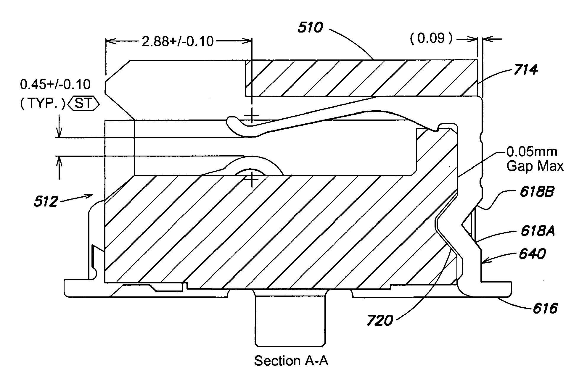
[0034]Applicants have recognized and appreciated that, though a standardized form factor for a connector provides many benefits, it can constrain design options, thereby limiting electrical performance of connectors made according to the standard. Applicants have recognized that improvements can be made to connector performance by appropriate selection of materials and shapes for elements of a connector. These improvements can be achieved even while staying within the form factor of standardized connectors, such as SFP connectors.

[0035]Such improvements may be used together, separately or in any suitable combination to increase the frequency range over which the connector may be used. Such techniques may be used to control various aspects of electrical performance, including the impedance of contact elements used to carry high speed signals within the connector. Changes may be made to provide pairs of signal contact elements that are designated as high speed signal conductors that h...


PUM


Abstract

Techniques for improving electrical performance of a connector. The techniques are compatible with the form factor of a standardized connector, such as an SFP connector or stacked SFP. The resulting connector has reduced insertion loss for high speed signals. Such techniques, which can be used separately or together, include shaping of conductive elements within the connector while still retaining the same mating contact arrangement. Changes may be made at the contact tail portions or in the intermediate portions where engagement to a connector housing occurs. The techniques also include the incorporation of lossy bridging members between conductive elements designated to be ground conductors. For connectors according to the stacked SFP configuration, multiple bridging members may be incorporated at multiple locations within the connector.

Description

FIELD OF THE INVENTION[0001]This invention relates generally to electrical connectors and more specifically to electrical connectors adapted to receive cable plug assemblies.RELATED TECHNOLOGY[0002]Electronic systems are frequently manufactured from multiple interconnected assemblies. Electronic devices, such as computers, frequently contain electronic components attached to printed circuit boards. One or more printed circuit boards may be positioned within a rack or other support structure and interconnected so that data or other signals may be processed by the components on different printed circuit boards.[0003]Frequently, interconnections between printed circuit boards are made using electrical connectors. To make such an interconnection, one electrical connector is attached to each printed circuit board to be connected, and those boards are positioned such that the connectors mate, creating signal paths between the boards. Signals can pass from board to board through the connec...

Claims


Application Information

Patent Timeline
Patent Type & Authority Applications(United States)
IPC IPC(8): H01R24/60
CPCH01R12/724H01R12/721H01R25/006
Inventor KIRK, BRIANKASTURI, VIJAY
Owner AMPHENOL CORP
Why Eureka
Try Eureka