
Methods and systems for detection and notification of blocked rail crossings

Active Publication Date: 2013-01-17
THE ISLAND RADAR
View PDF5 Cites 45 Cited by
  • Summary
  • Abstract
  • Description
  • Claims
  • Application Information

AI Technical Summary

Benefits of technology

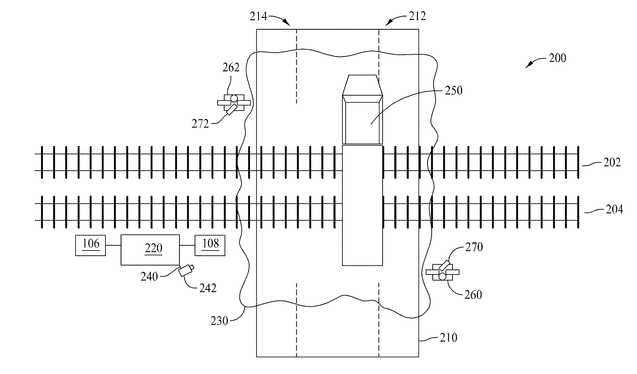
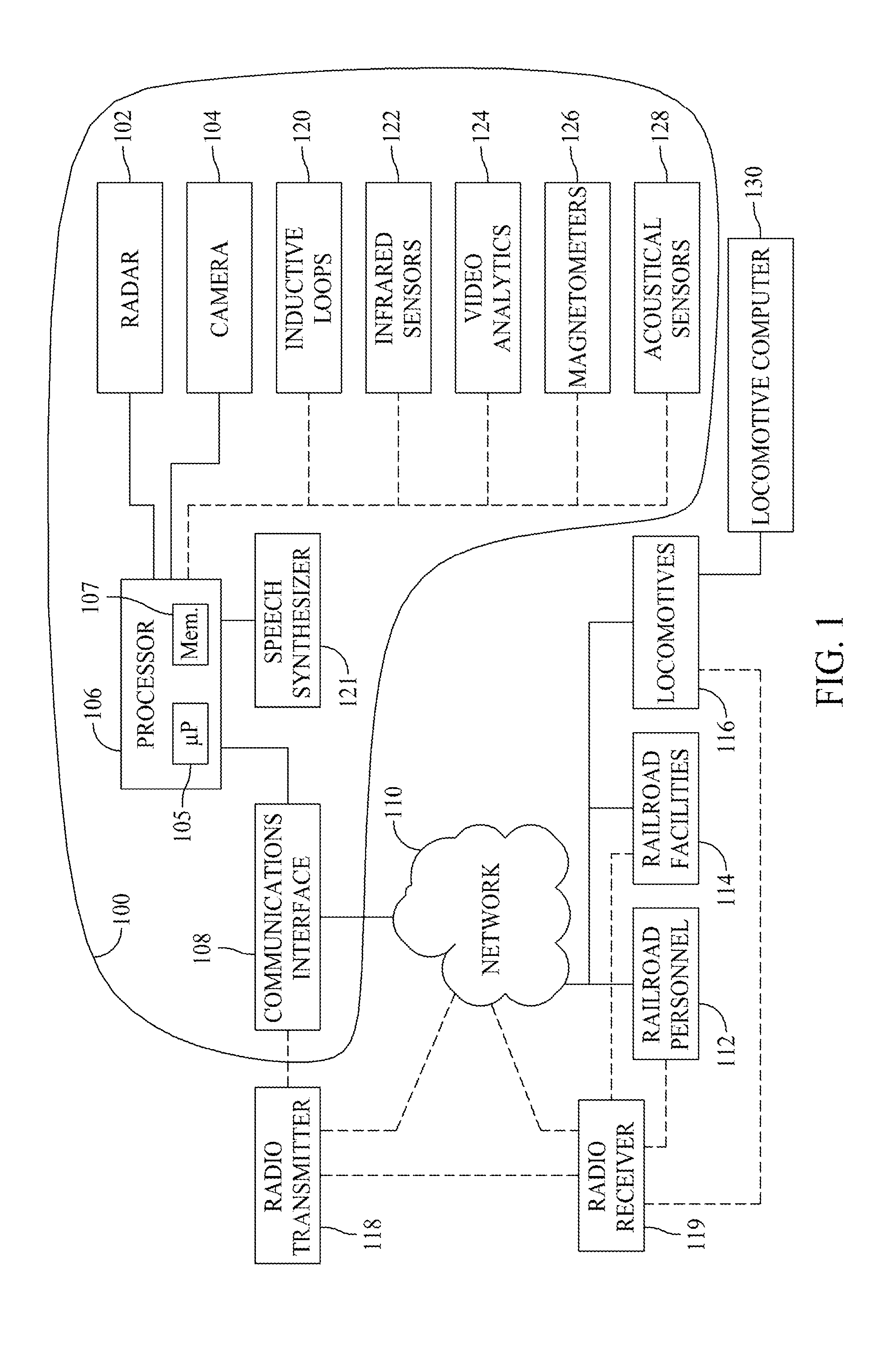
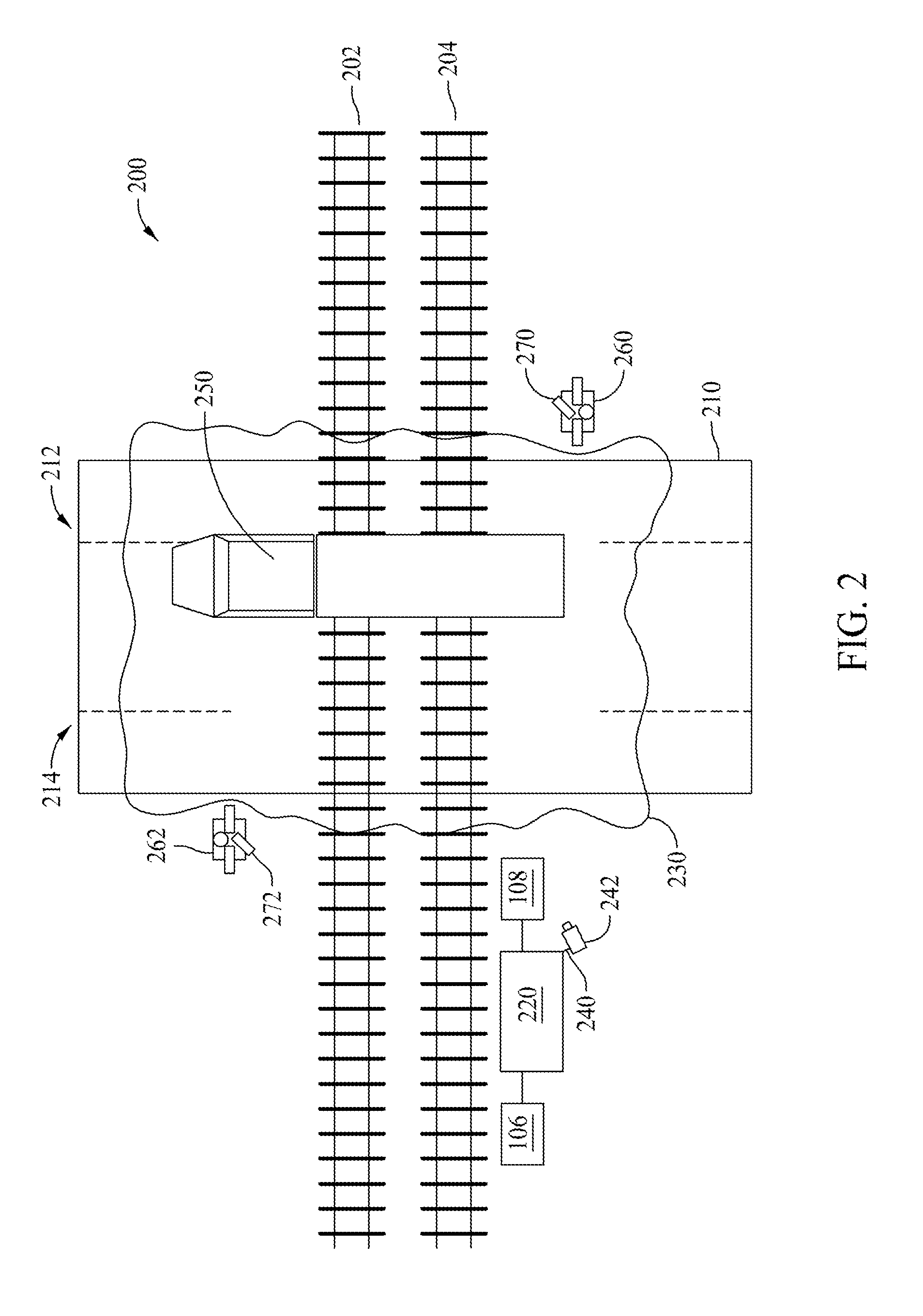
The patent describes a system that can detect when a rail crossing is blocked and notify people about it. The system includes a device that can communicate with external devices, like phones or computers. It uses a vehicle detection mechanism to see if there are any vehicles near the rail crossing. The device sends a signal to the external device indicating if there is a vehicle present. The processing device also sends visual data to help explain what's happening at the rail crossing. This helps people who are near the rail crossing to know what's happening and take appropriate action, like stopping a vehicle or alerting emergency responders.

Problems solved by technology

While the active warning systems are effective, risks persist.
One such risk is that associated with the instance of vehicles that are found within the crossing island, which is the area between barrier gates where the rails are located.
Such vehicles may be accidently or deliberately placed in such crossing islands.
For example, a vehicle may become disabled while within or near the crossing island.
Instances have occurred where automobile drivers have driven around the barrier gates only to find themselves trapped within the crossing island.
Instances have also occurred wherein motorists have also mistakenly driven their vehicles outside the crossing island and the Minimum Track Clearance Distance (MTCD) area or zone and onto the railroad tracks, with the vehicles becoming temporarily stuck on the tracks in the path of a potential approaching train.
At such speeds, locomotive operators and engineers have insufficient time to halt the train if such an obstruction is visually identified at or near an upcoming crossing.

Method used


Image

  • Methods and systems for detection and notification of blocked rail crossings
  • Methods and systems for detection and notification of blocked rail crossings
  • Methods and systems for detection and notification of blocked rail crossings

Examples


Embodiment Construction

[0014]The following discussion of exemplary and advantageous embodiments is presented for purposes of illustration and description of the inventive concepts disclosed, and is not intended to be exhaustive or limited to the particular embodiments in the form disclosed. Many modifications and variations of the concepts disclosed will be apparent to those of ordinary skill in the art. Further, different advantageous embodiments may provide different advantages as compared to other advantageous embodiments. The embodiment or embodiments selected are chosen and described in order to best explain the principles of the embodiments, the practical application of the concepts disclosed, and to enable others of ordinary skill in the art to understand the disclosure for various embodiments with various modifications as are suited to the particular uses contemplated. Method aspects implementing advantageous features will be in part apparent and in part explicitly discussed in the description bel...


PUM


Abstract

A blocked rail crossing detection and notification system is described. The system includes a processing device, a communications interface communicatively coupled to the processing device and operable for facilitating communications between the processing device and at least one external device, and at least one vehicle detection mechanism placed proximate to a rail grade crossing. The at least one vehicle detection mechanism is communicatively coupled to the processing device and operable to provide signals to the processing device indicative of the presence or non-presence of a vehicle within a defined area surrounding an intersection of a roadway and one or more railroad tracks. The processing device is further programmed to communicate the presence or non-presence of a vehicle along with supporting correlative visual data within the defined area to the at least one external device via the communications interface.

Description

CROSS REFERENCE TO RELATED APPLICATIONS[0001]This application claims the benefit of U.S. Provisional Patent Application Ser. No. 61 / 436,006 filed Jan. 25, 2011, the disclosure of which is hereby incorporated by reference in its entirety.BACKGROUND[0002]The field of the disclosure relates generally to railroad grade crossings, and more specifically, to methods and systems for detection and notification of blocked rail crossings.[0003]Train traffic in North America typically intersects with public streets and highways at railroad grade crossings. At such crossings, active and / or passive warning systems provide a notification to automotive traffic regarding the impending arrival of a train. The particular notifications provided are somewhat dependent on the street or highway intersecting the rail line. For example, where average train speeds or automotive traffic volume warrants, active warning systems are deployed which may include one or more of flashing lights, bells, and barrier ga...

Claims


Application Information

Patent Timeline
IPC IPC(8): B61L23/00
CPCB61L27/00B61L29/30
Inventor HILLEARY, THOMAS N.
Owner THE ISLAND RADAR
Learn More