Electric transaxle

Active Publication Date: 2013-01-24
KANZAKI KOKYUKOKI MFG
View PDF14 Cites 36 Cited by
  • Summary
  • Abstract
  • Description
  • Claims
  • Application Information

AI Technical Summary

Benefits of technology

[0009]An object of the present invention is to provide an electric transaxle configured so that lubricating fluid raised and splashed by gears is effectively supplied to a motor chamber of an electric motor so as to cool the electric motor and so

Problems solved by technology

However, this structure is available for only guiding fluid splashed by the gears rotating in one direction for forward traveling of the vehicle.
If the electric transaxle is adapted to a working vehicle that often reverses its traveling direction, fluid raised and splashed by the gears rotating in the direction for backward traveling of the vehicle is insufficiently supplied to the second fluid sump, thereby insufficiently lowering the level of the first fluid sump for reducing resistance of the first fluid sump to stirring of the gears, and thereby insufficiently supplying the motor chamber with fluid for cooling the electric motor from the second fluid sump.
Further, in the above-mentioned conventional electric transaxle, the fluid passa

Method used


Image

  • Electric transaxle
  • Electric transaxle
  • Electric transaxle

Examples


Embodiment Construction

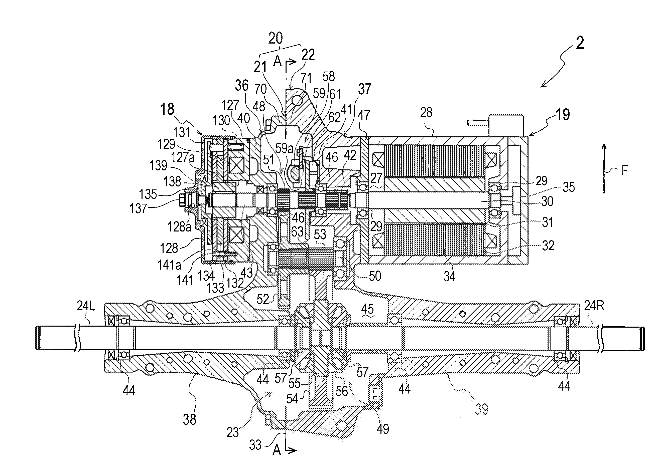
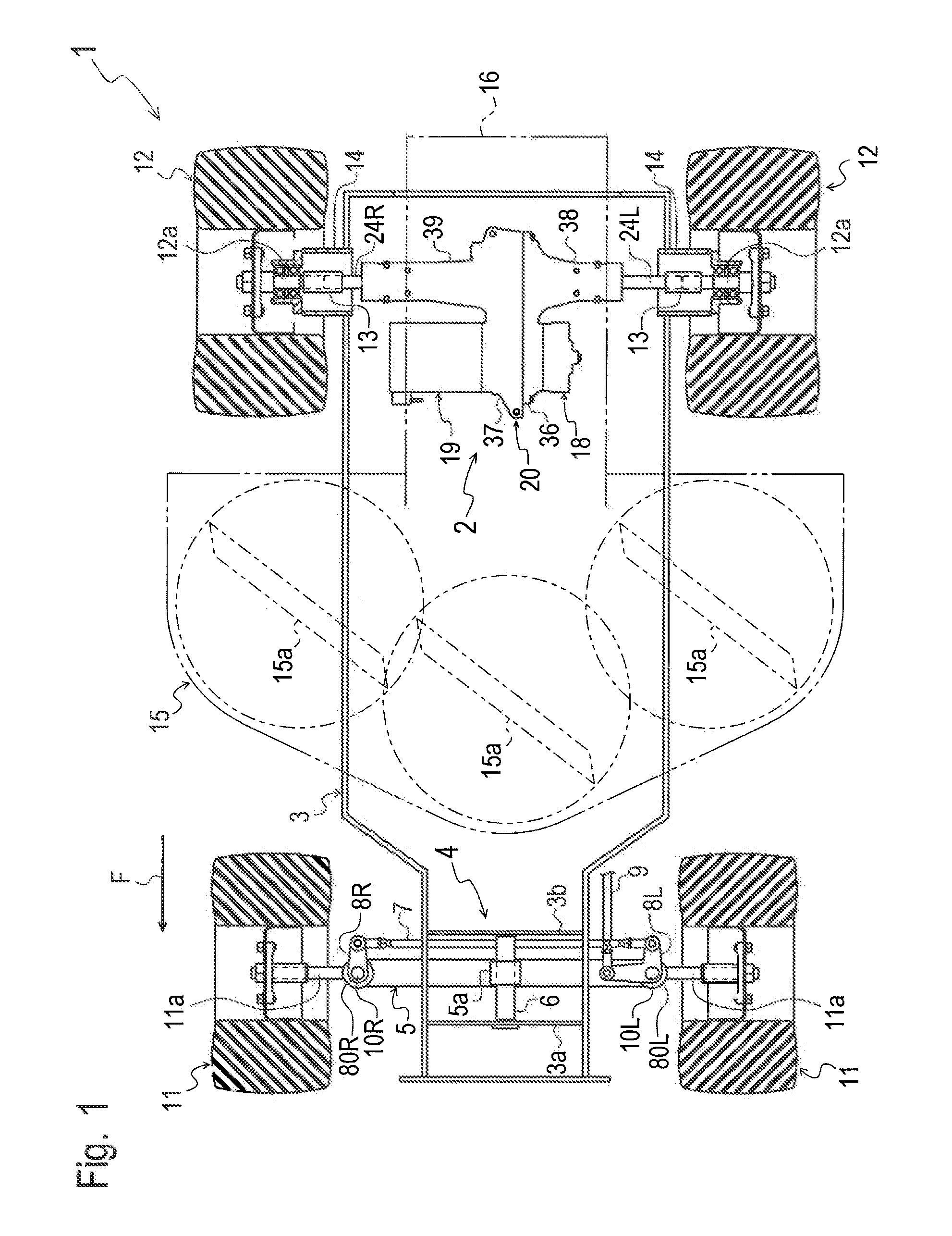
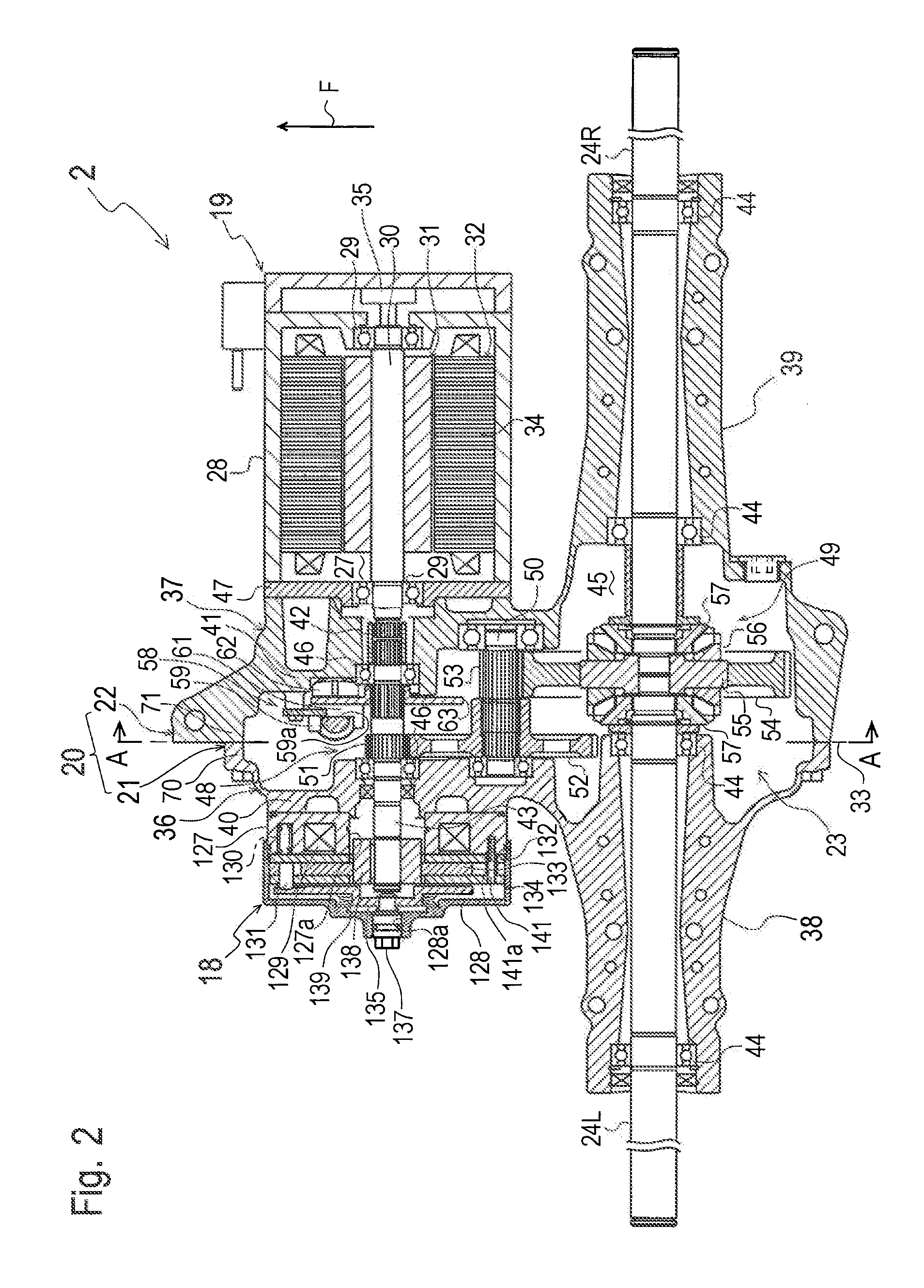
[0042]Some embodiments will be described hereinafter on an assumption that arrows F in some drawings are directed forward so as to correspond to the forward traveling direction of a vehicle 1 as shown in FIG. 1.

[0043]A general structure of vehicle 1 equipped with an electric transaxle (hereinafter, simply referred to “transaxle”) 2 will be described with reference to FIGS. 1 and 2. Vehicle 1 is a riding lawn mower, serving as a typical working vehicle, and having a vehicle body frame 3 extended in the fore-and-aft direction of vehicle 1. A front potion of vehicle body frame 3 supports an axle supporter 4 supporting right and left front wheels 11. A rear portion of vehicle body frame 3 supports transaxle 2 supporting right and left rear wheels 12.

[0044]Vehicle 1 is equipped with a mower deck 15 between front axle supporter 4 and rear transaxle 2. Mower deck 15 accommodates at least one rotary blade 15a (in this embodiment, three rotary blades 15a). A duct 16 for discharging grass mow...


PUM


Abstract

An electric transaxle according to the invention comprises a transaxle casing, an electric motor, an axle, a gear mechanism, first and second fluid sumps, and first and second fluid introduction passages. The transaxle casing defines a gear chamber therein. The electric motor includes a motor casing attached to the transaxle casing. The axle is supported by the transaxle casing. The gear mechanism transmits power from the electric motor to the axle. Fluid of the first fluid sump raised by driving the gear mechanism is supplied to the second fluid sump. The first fluid introduction passage introduces the fluid raised from the first fluid sump to the second fluid sump when the axle is rotated in a forward traveling direction. The second fluid introduction passage introduces the fluid raised from the first fluid sump to the second fluid sump when the axle is rotated in a backward traveling direction.

Description

BACKGROUND OF THE INVENTION[0001]1. Field of the Invention[0002]The present invention relates to an electric transaxle including an axle, an electric motor for driving the axle, a gear mechanism for transmitting power front the electric motor to the axle, and a transaxle casing incorporating the gear mechanism.[0003]2. Related Art[0004]Conventionally, as disclosed by JP H09-226394 A, there is a well-known electric transaxle including an axle, an electric motor for driving the axle, a gear mechanism for transmitting power from the electric motor to the axle, and a transaxle casing incorporating the gear mechanism. The transaxle casing defines a gear chamber incorporating the gear mechanism, and fluid for lubricating the gear mechanism is accumulated in a bottom portion of the gear chamber so as to serve as a fluid sump (hereinafter, referred to as “first fluid sump”), and the gear mechanism is submerged in the first fluid sump. Further, the transaxle casing is provided in an upper po...

Claims


Application Information

Patent Timeline
IPC IPC(8): F16H57/04
CPCB60K7/0007Y10T74/19995B60K2001/003B60K2001/001F16H57/0423F16H57/045F16H57/0457F16H57/0483
Inventor EBIHARA, TOMOYUKIHASHIMA, HIROAKISASAHARA, KENGO
Owner KANZAKI KOKYUKOKI MFG
Why Eureka
Try Eureka