Electrical Bushing

a technology of electrical bushings and bushings, applied in the direction of electrical equipment, basic electric elements, insulation bodies, etc., can solve the problem of limited physical space available for bushings, and achieve the effect of improving the relationship between voltage-withstanding properties and bushing diameter

Active Publication Date: 2013-01-31
HITACHI ENERGY SWITZERLAND AG
View PDF11 Cites 10 Cited by
  • Summary
  • Abstract
  • Description
  • Claims
  • Application Information

AI Technical Summary

Benefits of technology

[0007]An object of the present invention is to provide a bushing having an impr

Problems solved by technology

At the same time, the physical space ava

Method used


Image

  • Electrical Bushing
  • Electrical Bushing
  • Electrical Bushing

Examples


Embodiment Construction

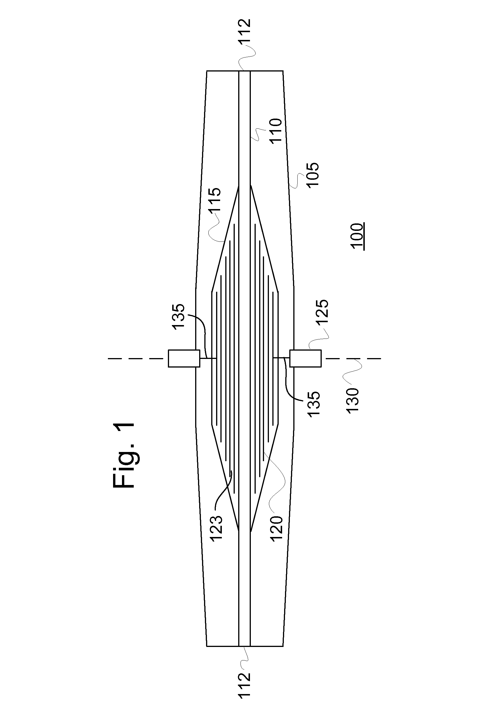
[0028]FIG. 1 schematically illustrates a bushing 100 comprising a hollow, elongate insulator 105 through which a conductor 110 extends. At each end of the conductor 110 is provided an electrical terminal 112 for connecting the conductor 110 to electrical systems or devices. Bushing 100 of FIG. 1 furthermore comprises a condenser core 115. In FIG. 1, the conductor 110 has been shown to form part of the bushing 100. However, some bushings 100 do not include a conductor 110, but include a pipe-shaped hole in the conductor location in which a conductor 110 may be inserted.

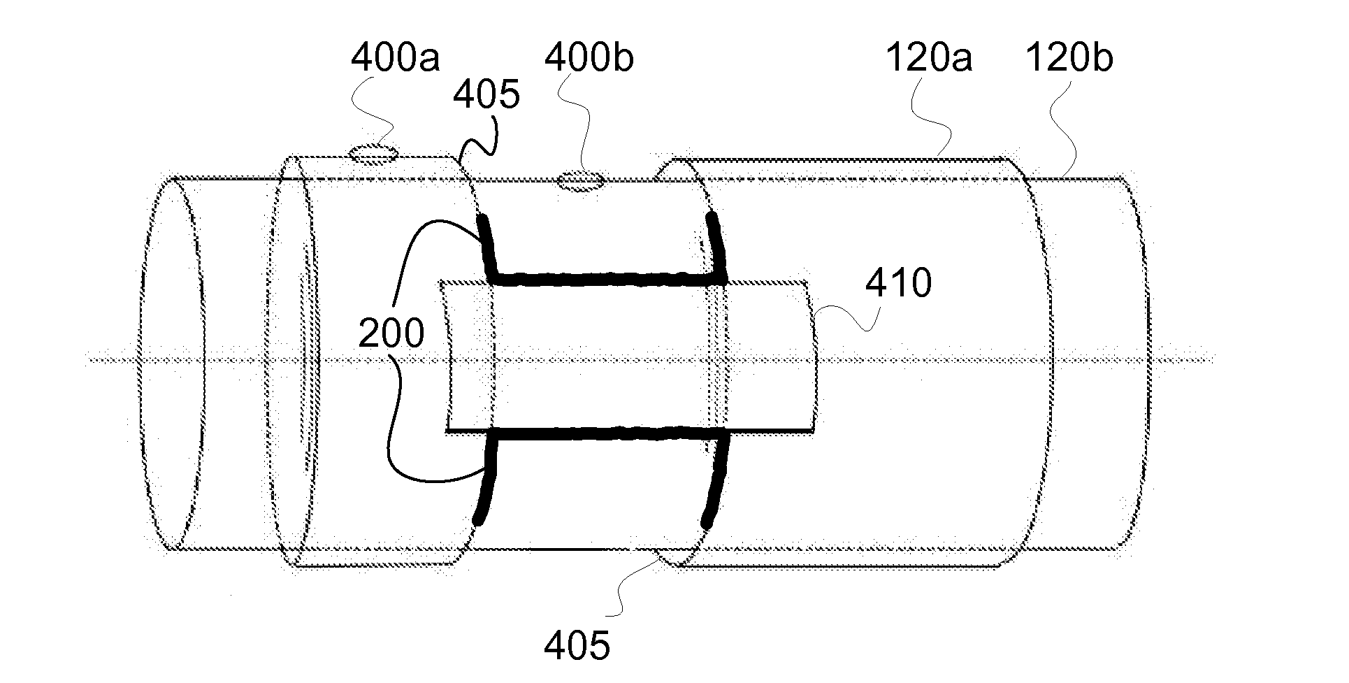
[0029]The condenser core 115 of FIG. 1 comprises a number of foils 120 which are separated by a dielectric insulator 123. The dielectric insulator 123 is typically made of a solid insulating material, such as oil- or resin impregnated paper. The foils 120 are typically coaxially arranged, and could for example be made of aluminium or other conducting material. The foils 120 could be integrated with the dielectric mater...


PUM


Abstract

An electrical bushing for providing electrical insulation of a conductor extending through the bushing is disclosed. The bushing includes: one conductive foil concentrically arranged around the conductor location; and one FGM part, made from a field grading material and partly arranged in the extension of part of a foil edge of a conductive foil. The FGM part and the conductive foil, in the extension of which the FGM part is arranged, are in electrical contact.

Description

FIELD OF THE INVENTION[0001]The present invention relates to the field of high voltage technology, and in particular to high voltage bushings for providing electrical insulation of a conductor.BACKGROUND OF THE INVENTION[0002]High voltage bushings are used for carrying current at high potential through a plane, often referred to as a grounded plane, where the plane is at a different potential than the current path. High voltage bushings are designed to electrically insulate a high voltage conductor, located inside the bushing, from the grounded plane. The grounded plane can for example be a transformer tank or a wall.[0003]In order to obtain a smoothening of the electrical potential distribution between the conductor and the grounded plane, a bushing often comprises a number of floating, coaxial foils made of a conducting material and coaxially surrounding the high voltage conductor, the coaxial foils forming a so called condenser core. The foils could for example be made of alumini...

Claims


Application Information

Patent Timeline
IPC IPC(8): H01B17/58
CPCH01B17/28H01F27/04H01B17/42H01B17/583
Inventor BORJESSON, JAN-AKEERIKSSON, GORANLAIHONEN, SARIPRADHAN, MANOJSJOBERG, PETERUNGE, MIKAEL
Owner HITACHI ENERGY SWITZERLAND AG
Why Eureka
Try Eureka