Power transmission device for vacuum interrupter and vacuum breaker having the same

Active Publication Date: 2013-01-31
LSIS CO LTD
View PDF4 Cites 2 Cited by
  • Summary
  • Abstract
  • Description
  • Claims
  • Application Information

AI Technical Summary

Benefits of technology

The patent describes a power transmission device for a vacuum interrupter and a vacuum breaker with the device. The device reduces the speed at which the two electrodes collide during a closing operation and helps to quickly move the movable electrode through a pre-arc region, which reduces the time it takes for the device to fully engage. The device also includes protrusions that help the cams move smoothly along each recess portion. Overall, the device improves the performance and reliability of the vacuum interrupter and breaker.

Problems solved by technology

Furthermore, as industrial equipment becomes large, an interruption capacity of the circuit breaker becomes also large.
Such impact may cause transformation of a fixed electrode and a movable electrode, and such transformation may lower performance of the vacuum interrupter.
In order to solve such problems, if the entire closing speed is made to be slow, closing time becomes long.
As a result, time for which a pre-arc occurring when a vacuum insulation state disappears during a closing operation is maintained is long.
Such long duration for which pre-arc has occurred badly influences on performance of the vacuum breaker.
Firstly, energy stored in a compression spring of the adjuster is applied to the movable electrode as it is. As a result, the movable electrode moves while maintaining the same speed during a closing operation, thereby having a significantly increased contact speed with the fixed electrode. This may increase an impact amount between the movable electrode and the fixed electrode, thereby causing damages of components of the movable electrode or the fixed electrode or the insulating container.

Method used


Image

  • Power transmission device for vacuum interrupter and vacuum breaker having the same
  • Power transmission device for vacuum interrupter and vacuum breaker having the same
  • Power transmission device for vacuum interrupter and vacuum breaker having the same

Examples


Embodiment Construction

[0032]Description will now be given in detail of the exemplary embodiments, with reference to the accompanying drawings. For the sake of brief description with reference to the drawings, the same or equivalent components will be provided with the same reference numbers, and description thereof will not be repeated.

[0033]Hereinafter, a power transmission device for a vacuum interrupter, and a vacuum breaker having the same according to the present invention will be explained in more details with reference to the attached drawings.

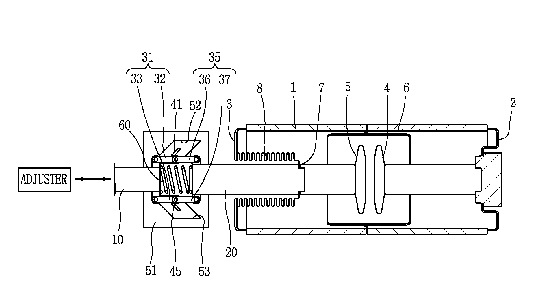
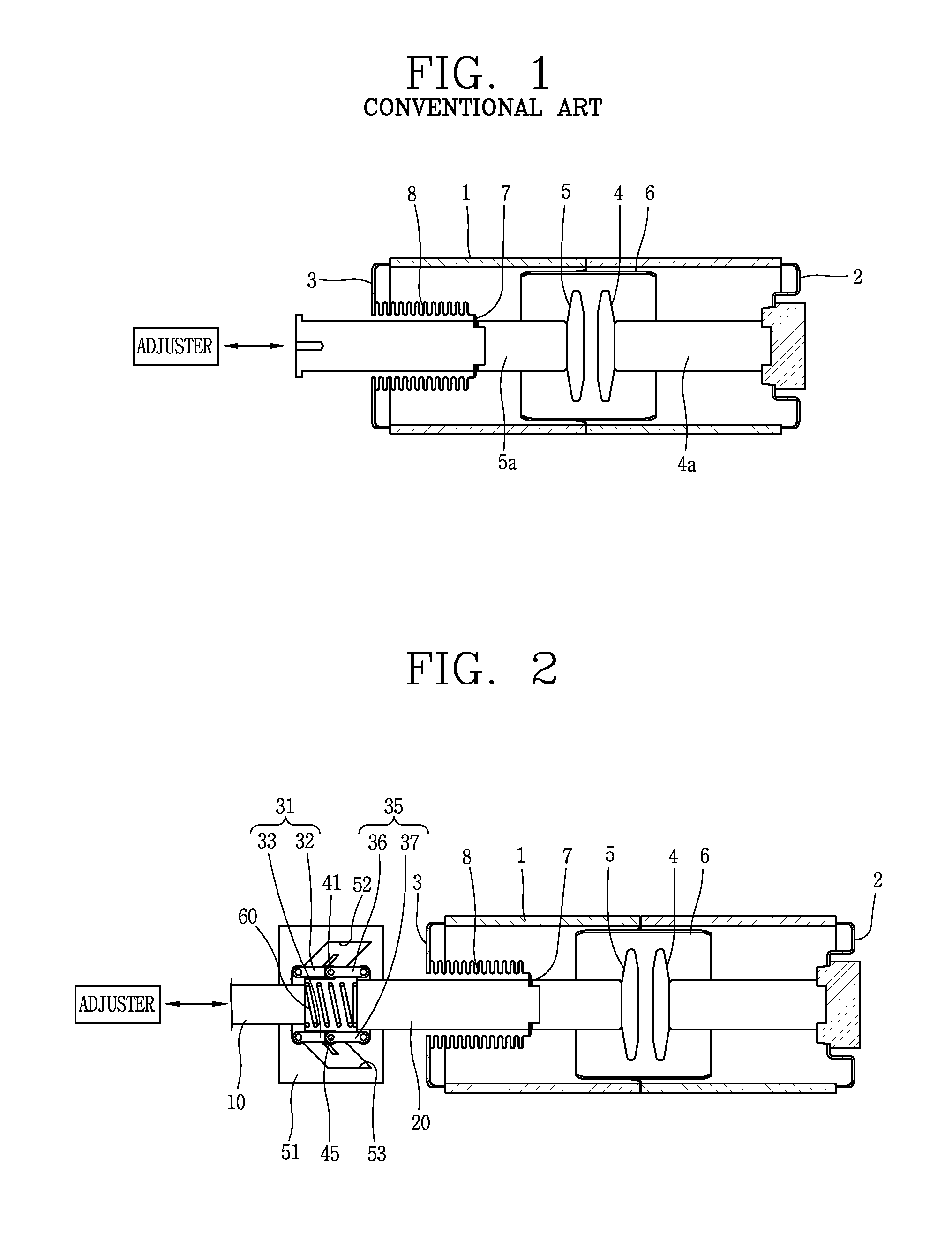
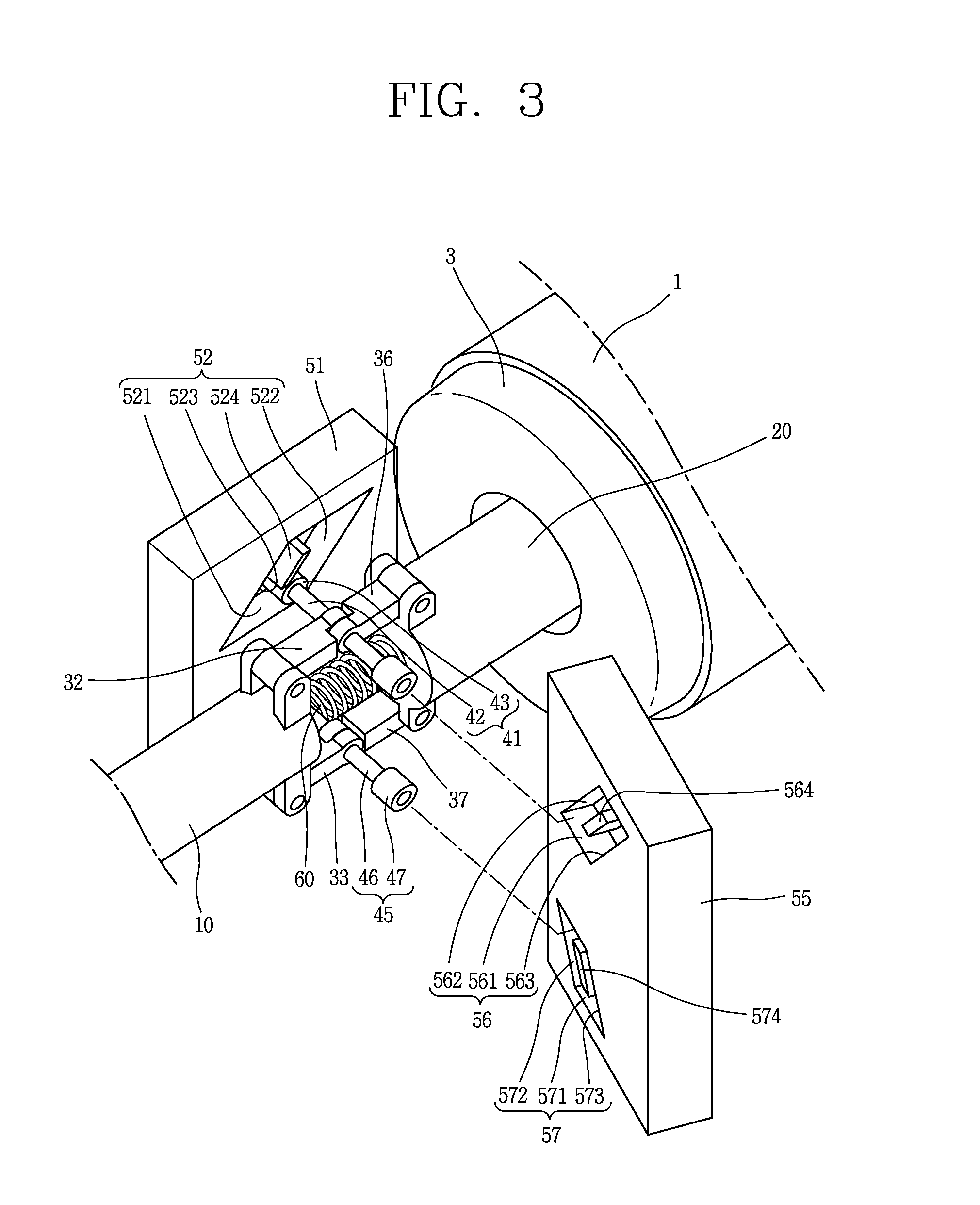
[0034]FIG. 2 is a sectional view of a vacuum interrupter and a power transmission device according to the present invention, FIG. 3 is a perspective view illustrating the power transmission device of FIG. 2, and FIGS. 4 and 5 are sectional views illustrating operation states of the vacuum interrupter and the power transmission device of FIG. 2.

[0035]As shown in FIGS. 2 and 3, the vacuum breaker according to the present invention includes a power transmission...


PUM


Abstract

Disclosed are a power transmission device for a vacuum interrupter, and a vacuum breaker having the same. The device includes: a driving link coupled to an adjuster; a driven link coupled to a movable electrode of a vacuum interrupter; connection links configured to connect the driving link and the driven link with each other, and coupled to the driving link and the driven link such that an interval between the driving link and the driven link is varied; cams coupled to the connection links in a perpendicular direction; and cam guides having guide recesses for slidably coupling the cams, and configured to guide the interval between the driving link and the driven link to be changed.

Description

CROSS-REFERENCE TO RELATED APPLICATION[0001]Pursuant to 35 U.S.C. §119(a), this application claims the benefit of earlier filing date and right of priority to Korean Application No. 10-2011-0073803, filed on Jul. 25, 2011, the contents of which is incorporated by reference herein in its entirety.BACKGROUND OF THE INVENTION[0002]1. Field of the Invention[0003]The present disclosure relates to a power transmission device for a vacuum interrupter applied to a vacuum circuit breaker, and a vacuum breaker having the same.[0004]2. Background of the Invention[0005]Generally, a vacuum interrupter of a vacuum circuit breaker is a main extinguishing device applied to a vacuum breaker, a vacuum switching device, a vacuum connector, etc. for interrupting a load current or an accident current in a power system. The vacuum circuit breaker for controlling power transmission and protecting a power system has advantages such as a large interruption capacity, high reliability, high stability, and sma...

Claims


Application Information

Patent Timeline
IPC IPC(8): H01H5/04
CPCH01H33/666H01H2003/323H01H3/48H01H3/46H01H3/42
Inventor YANG, JAE MIN
Owner LSIS CO LTD
Why Eureka
Try Eureka