Parallel separation system

a separation system and parallel technology, applied in the direction of filtration separation, separation process, instruments, etc., can solve the problem of reducing separation efficiency, and achieve the effect of improving separation efficiency and uniform flow

Pending Publication Date: 2013-01-31
CYTIVA BIOPROCESS R&D AB
View PDF3 Cites 7 Cited by
  • Summary
  • Abstract
  • Description
  • Claims
  • Application Information

AI Technical Summary

Benefits of technology

[0003]One object of the invention is to improve the separation efficiency in a parallel assembly of separation modules by achieving a uniform flow over all individual modules in the parallel assembly.

Problems solved by technology

However, there are a number of problems associated with this concept.
One of the problems is that the separation efficiency will decrease due to non-uniform flow over the individual modules in the parallel assembly.

Method used


Image

  • Parallel separation system
  • Parallel separation system
  • Parallel separation system

Examples


Embodiment Construction

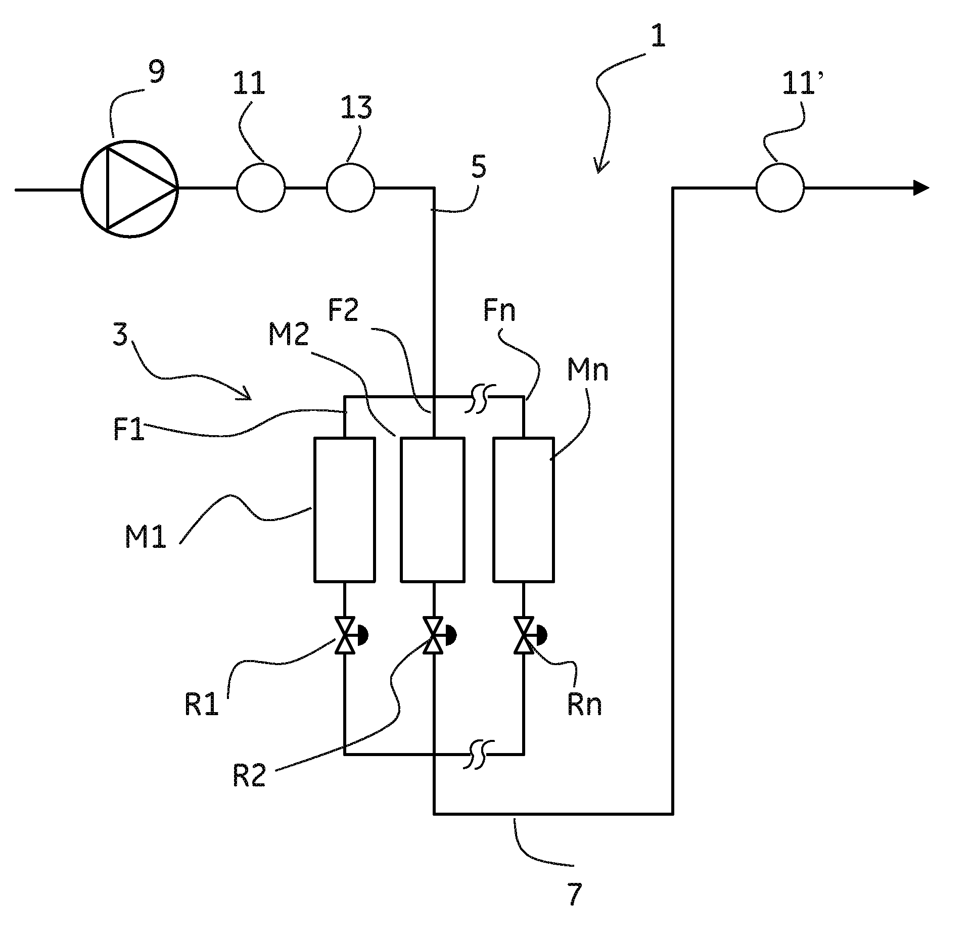
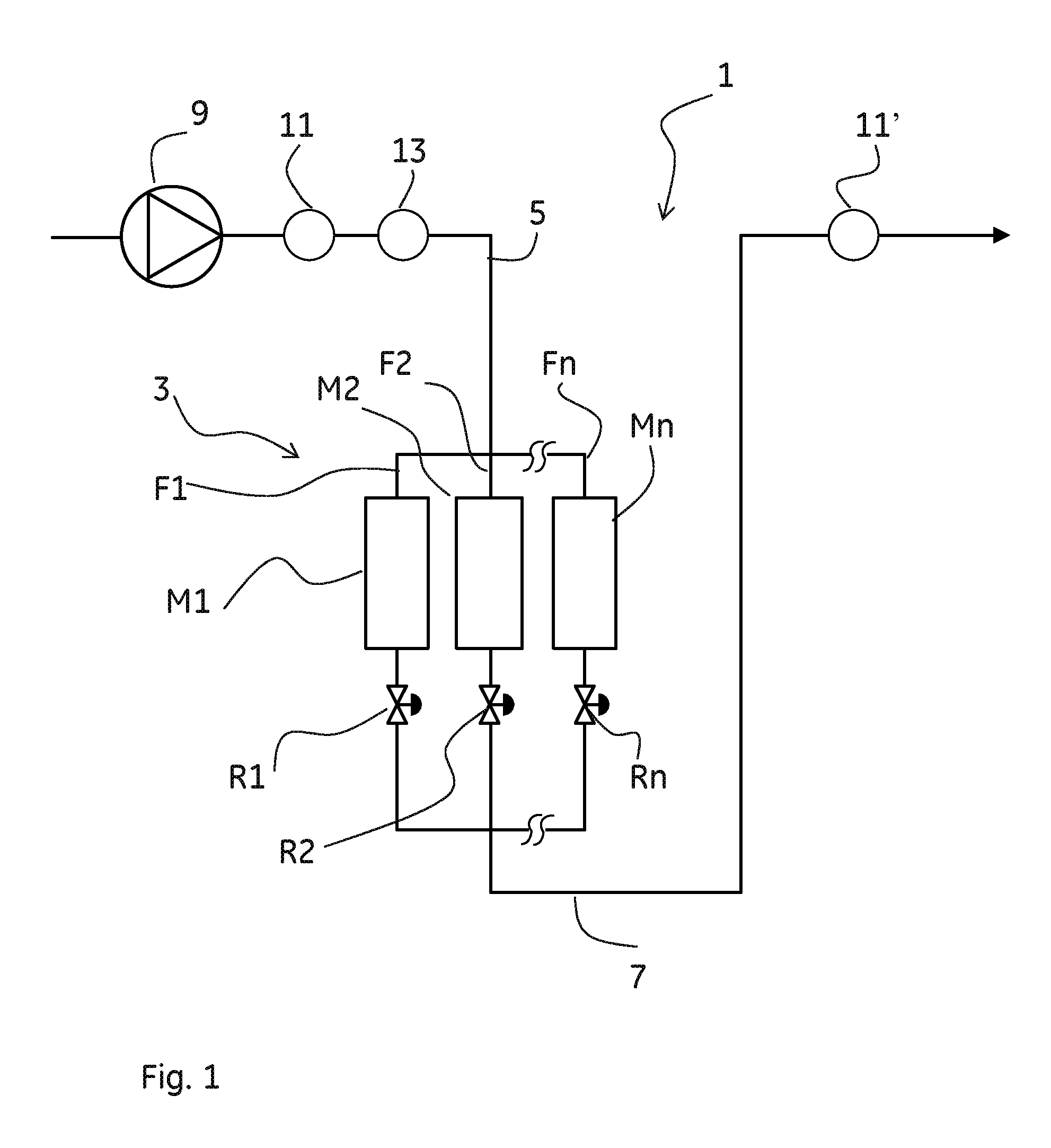
[0016]FIG. 1 shows schematically a separation system 1 comprising a parallel assembly 3 of separation modules M1, M2, . . . Mn according to one embodiment of the invention. The parallel assembly 3 comprises a number of parallel fluid paths F1, F2, . . . Fn. Three fluid paths are shown here but it could be any number of parallel fluid paths. Each fluid path F1, F2, . . . Fn comprises a separation module M1, M2, . . . Mn. According to the invention each fluid path F1, F2, . . . Fn also comprises an adjustable flow restrictor R1, R2, . . . Rn. The adjustable flow restrictors R1, R2, . . . Rn should be possible to open completely, i.e. adjust to a position where no flow restriction is provided. Suitably the flow restrictors should also be possible to close completely, i.e. adjust such that no flow at all can pass. Alternatively or complementary a valve can be provided in each fluid path F1, F2, . . . Fn such that the fluid paths can be opened or closed. The separation system 1 further c...


PUM

PropertyMeasurementUnit
flow rateaaaaaaaaaa
flow rateaaaaaaaaaa
Mnaaaaaaaaaa

Abstract

A method in a separation system comprising parallel fluid paths each comprising a separation module.According to the invention said method comprises the steps of:providing an adjustable flow restrictor in each fluid path;identifying the fluid path with highest hydraulic resistance by measuring the hydraulic resistance of each fluid path sequentially and separately while stopping the fluid flow through all other fluid paths;adjusting the hydraulic resistance of each of the parallel fluid paths to be substantially the same by adjusting the adjustable flow restrictor in each fluid path sequentially and separately while stopping the fluid flow through all other fluid paths, such that the hydraulic resistance of said fluid path is equal or higher than the resistance of the fluid path identified to have the highest hydraulic resistance.

Description

TECHNICAL FIELD OF THE INVENTION[0001]The present invention relates to a method in a separation system comprising parallel fluid paths each comprising a separation module and to system comprising a number of parallel fluid paths, wherein each parallel fluid path comprises a separation module.BACKGROUND OF THE INVENTION[0002]The use of separation modules, such as chromatography columns or cartridges, in a parallel configuration has a potential to reduce cost and increase flexibility in pilot and process scale bio-manufacturing. However, there are a number of problems associated with this concept. One of the problems is that the separation efficiency will decrease due to non-uniform flow over the individual modules in the parallel assembly.SUMMARY[0003]One object of the invention is to improve the separation efficiency in a parallel assembly of separation modules by achieving a uniform flow over all individual modules in the parallel assembly.[0004]This is achieved in a method accordi...

Claims


Application Information

Patent Timeline
Patent Type & Authority Applications(United States)
IPC IPC(8): B01J47/14B01D15/18
CPCB01D15/18G01N30/466G01N30/32G01N30/8658G01N2030/324
Inventor GEBAUER, KLAUS
Owner CYTIVA BIOPROCESS R&D AB
Why Eureka
Try Eureka