
Convergence Rate of FUll Wavefield Inversion Using Spectral Shaping

a spectral shaping and wavefield technology, applied in the field of geophysical prospecting, can solve the problems of high computational cost, high cost of global optimization methods, and high computational cost of iterative inversion, and achieve the effect of reducing misfi

Active Publication Date: 2013-01-31
EXXONMOBIL UPSTREAM RES CO
View PDF7 Cites 34 Cited by
  • Summary
  • Abstract
  • Description
  • Claims
  • Application Information

AI Technical Summary

Benefits of technology

The patent is about a method for improving the accuracy of seismic data to better understand the structure of underground regions. It uses a process called iterative inversion to update a current model of the data with new information to reduce any errors that might be present. The method controls the frequency spectrum of the model to match what is already known about the subsurface region. This helps to make the model more accurate and reliable for analyzing the data.

Problems solved by technology

Iterative inversion usually produces a more accurate model than non-iterative inversion, but is much more expensive to compute.
Unfortunately global optimization methods typically converge extremely slowly and therefore most geophysical inversions are based on local cost function optimization.
Unfortunately, iterative inversion is so computationally expensive that it is impractical to apply it to many problems of interest.
This high computational expense is the result of the fact that all inversion techniques require many compute intensive simulations.
The problem is exacerbated for iterative inversion, because the number of simulations that must be computed is proportional to the number of iterations in the inversion, and the number of iterations required is typically on the order of hundreds to thousands.
Inversion methods based on encoded simultaneous simulation often suffer from cross-talk noise contaminating the inversion result and are commonly limited by the data acquisition configuration (recording data with stationary receivers is a requirement for several of the methods).
Methods based on coherent summation typically lead to loss of information.

Method used


Image

  • Convergence Rate of FUll Wavefield Inversion Using Spectral Shaping
  • Convergence Rate of FUll Wavefield Inversion Using Spectral Shaping
  • Convergence Rate of FUll Wavefield Inversion Using Spectral Shaping

Examples


examples

[0049]An example illustrating how the Full Wavefield Inversion process can be very slow to converge is shown in FIGS. 6, 7 and 8, illustrating the convergence behavior for a small-size 2D problem. Some of the plots present in all three figures are the cumulative model update (601, 701, 801), a simulated shot gather (602, 702, 802) and the data residual for this gather (603, 703, 803), and a comparison of the frequency spectra for real (604, 704, 804) and simulated (605, 705, 805) shot gathers. After 10 inversion iterations (FIG. 6) there is still considerable mismatch between the real and synthetic data, as is evident from an inspection of the data residuals (603) and gather spectra (604, 605). The match has considerably improved after 50 iterations (FIG. 7), but inspection of the spectra (704, 705) reveals that there are still differences for the lower frequencies. It takes about 100 iterations (FIG. 8) to reach a more complete match and, even then, there are still differences in t...


PUM


Abstract

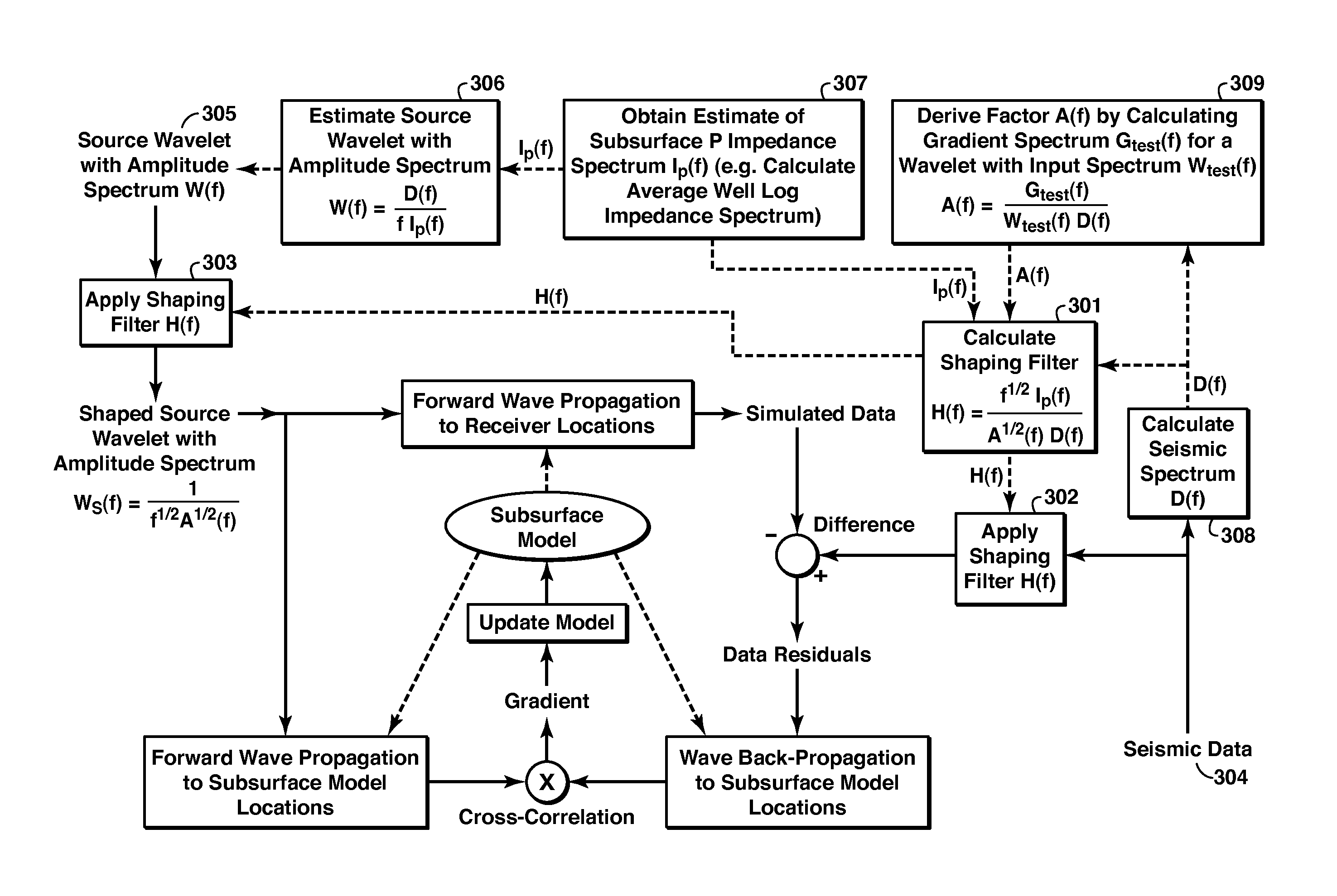
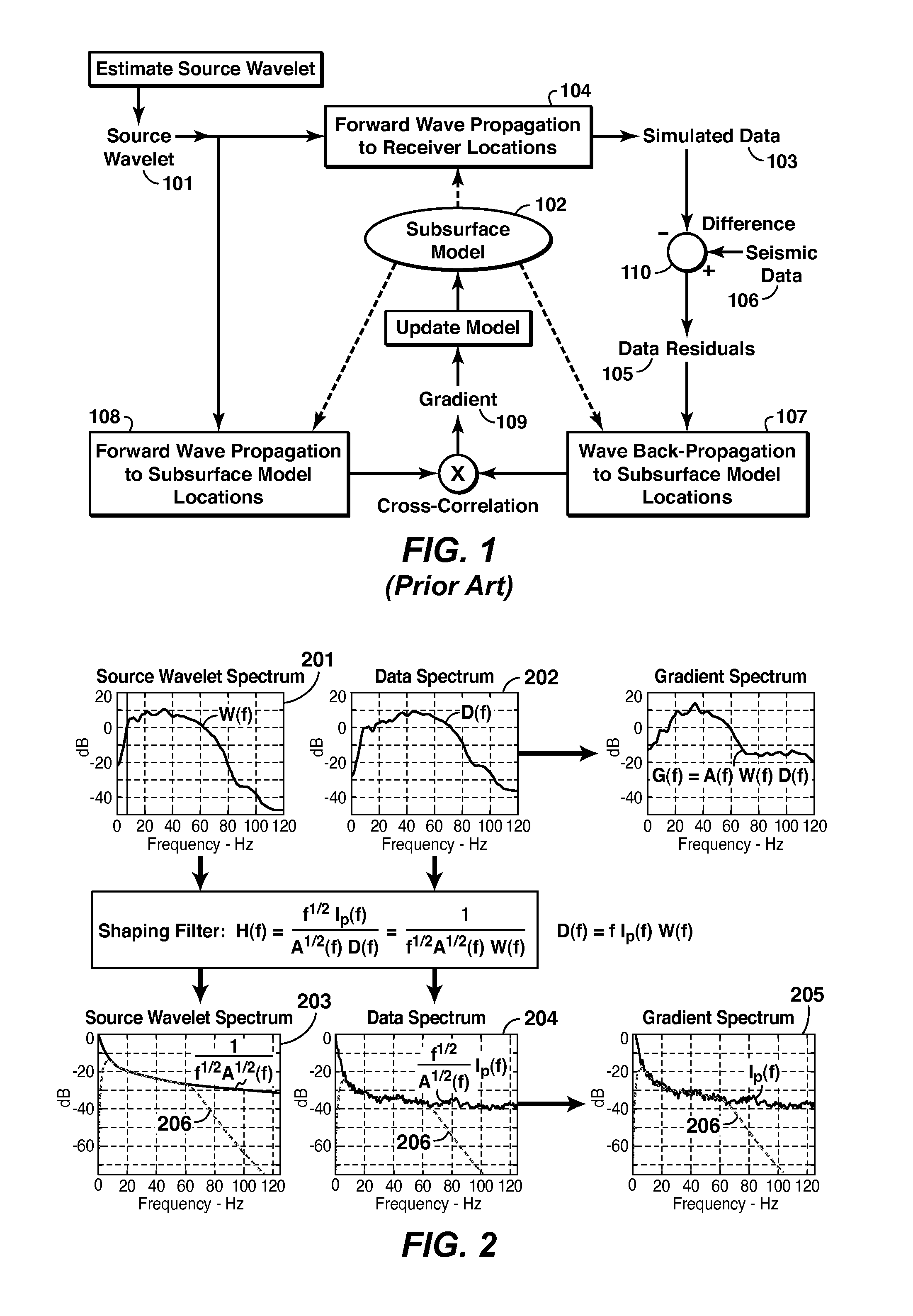
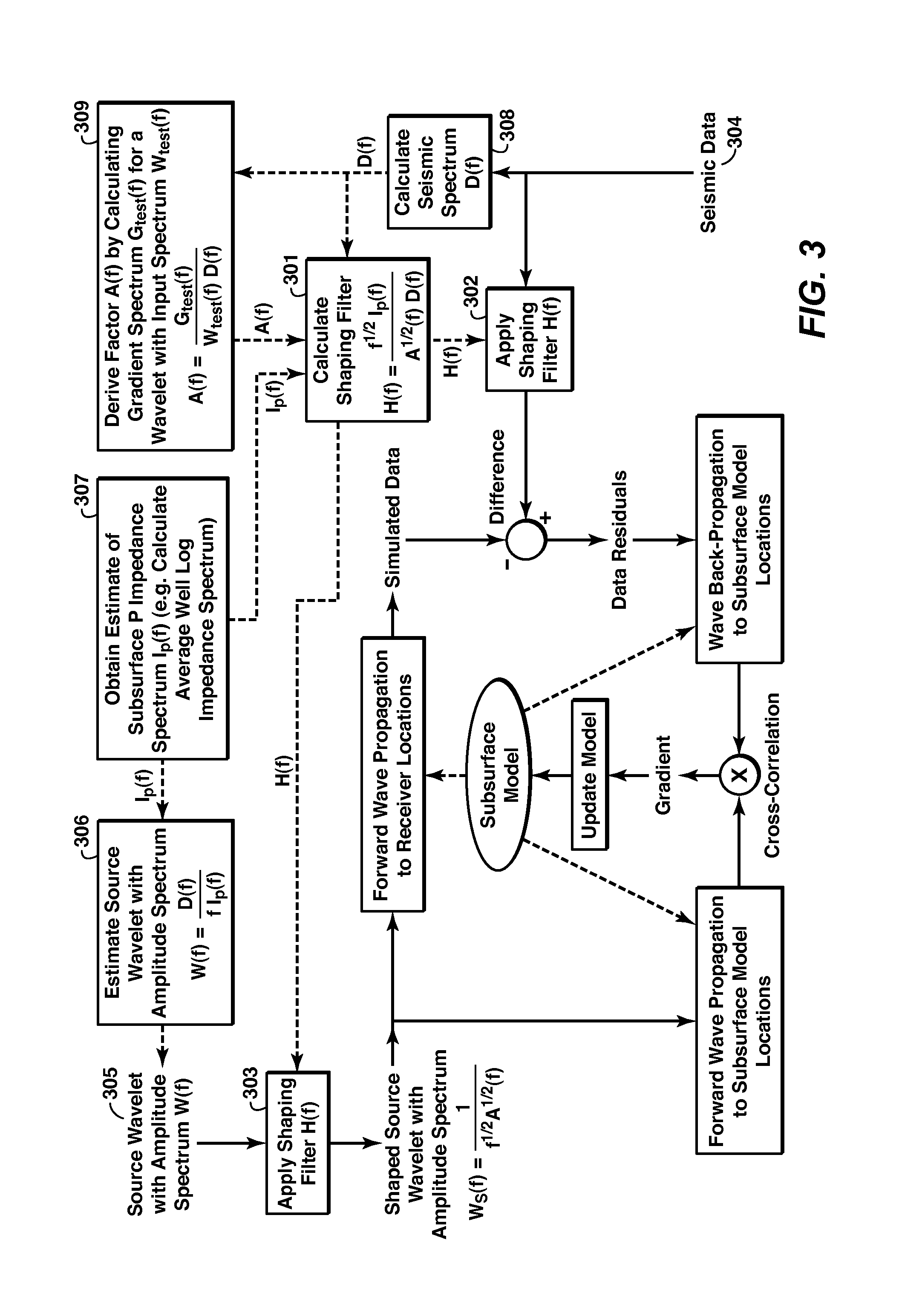
Method for speeding up iterative inversion of seismic data (106) to obtain a subsurface model (102), using local cost function optimization. The frequency spectrum of the updated model at each iteration is controlled to match a known or estimated frequency spectrum for the subsurface region, preferably the average amplitude spectrum of the subsurface P-impedance. The controlling is done either by applying a spectral-shaping filter to the source wavelet (303) and to the data (302) or by applying the filter, which may vary with time, to the gradient of the cost function (403). The source wavelet's amplitude spectrum (before filtering) should satisfy D(f)=fIp(f)W(f), where f is frequency, D(f) is the average amplitude spectrum of the seismic data, and Ip(f) is the average amplitude spectrum for P-impedance in the subsurface region (306,402) or an approximation thereof.

Description

CROSS-REFERENCE TO RELATED APPLICATION[0001]This application claims priority from both U.S. Provisional Patent Application No. 61 / 469,478 filed on Mar. 30, 2011, entitled Improving Convergence Rate of Full Wavefield Inversion Using Spectral Shaping and U.S. Provisional Patent Application No. 61 / 508,440 filed on Jul. 15, 2011 entitled Convergence Rate of Full Wavefield Inversion Using Spectral Shaping, both of which are incorporated by reference herein in their entirety.FIELD OF THE INVENTION[0002]This invention relates generally to the field of geophysical prospecting and, more particularly to inversion of seismic data, a broad term used to signify a process of building a model of the subsurface based on recorded seismic data. Specifically, the invention is a method for improving the convergence rate of full wavefield inversion using spectral shaping. The term Full Wavefield Inversion (“FWI”) is used to signify a type of inversion method aimed at generating subsurface models that ca...

Claims


Application Information

Patent Timeline
IPC IPC(8): G01V1/36
CPCG01V1/28G01V2210/67G01V2210/66
Inventor ROUTH, PARTHA S.LAZARATOS, SPYRIDON K.BAUMSTEIN, ANATOLYCHIKICHEV, IVANWANG, KE
Owner EXXONMOBIL UPSTREAM RES CO
Learn More