Signal processing apparatus and signal processing method, encoder and encoding method, decoder and decoding method, and program

a signal processing and signal processing technology, applied in the field of signal processing apparatus and signal processing method, can solve the problems of loss of original sound, deterioration of sound quality, loss of sound quality, etc., and achieve the effect of high sound quality

Active Publication Date: 2013-01-31
SONY CORP
View PDF4 Cites 78 Cited by
  • Summary
  • Abstract
  • Description
  • Claims
  • Application Information

AI Technical Summary

Benefits of technology

[0048]According to the first embodiment to the fourth embodiment, it is possible to reproduce music signal with high sound quality by expansion of a frequency band.

Problems solved by technology

However, since sound in a high band can be perceived slightly by human, if sound is produced and output from the decoded music signal obtained by decoding the encoded data, suffers a loss of sound quality whereby a sense of realism of an original sound is lost and a sound quality deterioration such a blur of sound occurs.

Method used


Image

  • Signal processing apparatus and signal processing method, encoder and encoding method, decoder and decoding method, and program
  • Signal processing apparatus and signal processing method, encoder and encoding method, decoder and decoding method, and program
  • Signal processing apparatus and signal processing method, encoder and encoding method, decoder and decoding method, and program

Examples


first embodiment

1. First Embodiment

[0112]In a first embodiment, a process that expands a frequency band (hereinafter, referred to as a frequency band expansion process) is performed with respect to a signal component of a low band after decoding obtained by decoding encoded data using a high cancelation encoding method.

[Functional Configuration Example of Frequency Band Expansion Apparatus]

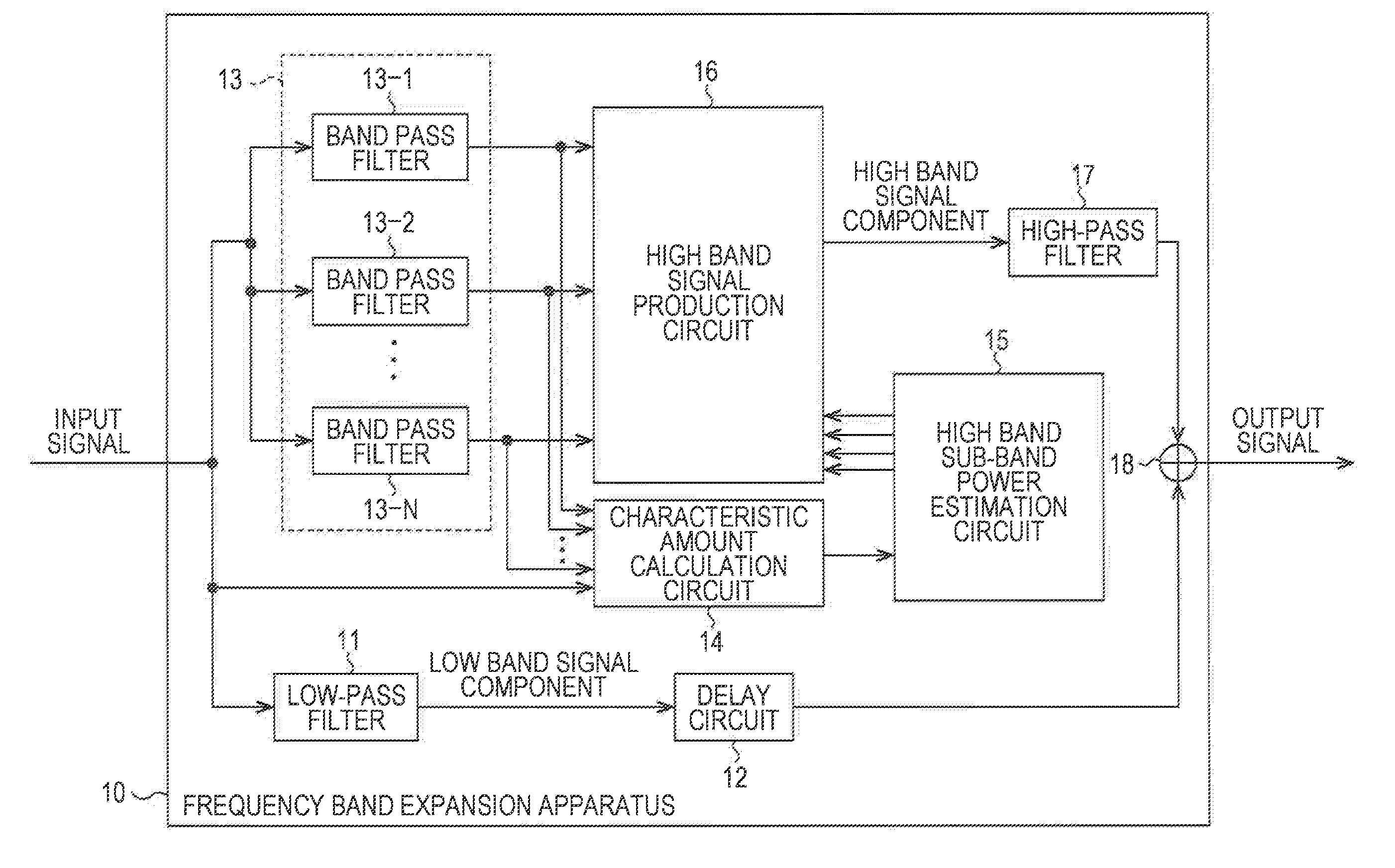
[0113]FIG. 3 illustrates a functional configuration example of a frequency band expansion apparatus according to the present invention.

[0114]A frequency band expansion apparatus 10 performs a frequency band expansion process with respect to the input signal by setting a signal component of the low band after decoding as the input signal and outputs the signal after the frequency band expansion process obtained by the result as an output signal.

[0115]The frequency band expansion apparatus 10 includes a low-pass filter 11, a delay circuit 12, a band pass filter 13, a characteristic amount calculation circuit 14, a ...

second embodiment

2. Second Embodiment

[0231]In a second embodiment, encoding processing and decoding processing in the high band characteristic encoding method by the encoder and the decoder are performed.

[Functional Configuration Example of Encoder]

[0232]FIG. 11 illustrates a functional configuration example of the encoder to which the present invention is applied.

[0233]An encoder 30 includes a 31, a low band encoding circuit 32, a sub-band division circuit 33, a characteristic amount calculation circuit 34, a pseudo high band sub-band power calculation circuit 35, a pseudo high band sub-band power difference calculation circuit 36, a high band encoding circuit 37, a multiplexing circuit 38 and a low band decoding circuit 39.

[0234]The low-pass filter 31 filters an input signal using a predetermined cutoff frequency and supplies a signal of a low band lower than a cutoff frequency (hereinafter, referred to as a low band signal) as signal after filtering to the low band encoding circuit 32, a sub-band...

third embodiment

3. Third Embodiment

[Functional Configuration Example of Encoder]

[0308]In addition, although it was described that the pseudo high band sub-band power difference ID is output from the encoder 30 to the decoder 40 as the high band encoded data, the coefficient index for obtaining the decoded high band sub-band power estimation coefficient may be set as the high band encoded data.

[0309]In this case, the encoder 30, for example, is configured as illustrated in FIG. 18. In addition, in FIG. 18, parts corresponding to parts in FIG. 11 has the same numeral reference and the description thereof is suitably omitted.

[0310]The encoder 30 in FIG. 18 is the same expect that the encoder 30 in FIG. 11 and the low band decoding circuit 39 are not provided and the remainder is the same.

[0311]In the encoder 30 in FIG. 18, the characteristic amount calculation circuit 34 calculates the low band sub-band power as the characteristic amount by using the low band sub-band signal supplied from the sub-band...


PUM


Abstract

The present invention relates to a signal processing apparatus and a signal processing method, an encoder and an encoding method, a decoder and a decoding method, and a program capable of reproducing music signal having a better sound quality by expansion of frequency band.
An encoder sets an interval including 16 frames as interval section to be processed, outputs high band encoded data for obtaining the high band component of an input signal and low band encoded data obtained by encoding the low band signal of the input signal for each section to be processed. In this case, for each frame, a coefficient used in estimation of the high band component is selected and the section to be processed is divided into continuous frame segments including continuous frames from which the coefficient with the same section to be processed is selected. In addition, high band encoded data is produced which includes data including information indicating a length of each continuous frame segment, information indicating the number of continuous frame segments included in the section to be processed and a coefficient index indicating the coefficient selected in each continuous frame segment. The present invention is applicable to the encoder.

Description

TECHNICAL FIELD[0001]The present invention relates to a signal processing apparatus and a signal processing method, an encoder and an encoding method, a decoder and a decoding method, and a program, and more particularly to a signal processing apparatus and a signal processing method, an encoder and an encoding method, a decoder and a decoding method, and a program for reproducing a music signal with improved sound quality by expansion of a frequency band.BACKGROUND ART[0002]Recently, music distribution services for distributing music data via the internet have been increased. The music distribution service distributes, as music data, encoded data obtained by encoding a music signal. As an encoding method of the music signal, an encoding method has been commonly used in which the encoded data file size is suppressed to decrease a bit rate so as to save time during download.[0003]Such an encoding method of the music signal is broadly divided into an encoding method such as MP3 (MPEG ...

Claims


Application Information

Patent Timeline
Patent Type & Authority Applications(United States)
IPC IPC(8): H04R5/00G10L19/02G10L19/16G10L21/038
CPCG10L21/038G10L19/0204G10L19/167G10L21/0388G10L19/16G10L21/04G10L19/0208
Inventor YAMAMOTO, YUKICHINEN, TORUHONMA, HIROYUKIMITSUFUJI, YUHKI
Owner SONY CORP
Why Eureka
Try Eureka