
Multi-component duplex printer

Inactive Publication Date: 2013-01-31
EASTMAN KODAK CO
View PDF1 Cites 1 Cited by
  • Summary
  • Abstract
  • Description
  • Claims
  • Application Information

AI Technical Summary

Benefits of technology

The present invention allows for printing both simplex and duplex print jobs, as well as duplex print jobs with specific components on different sides. The printer can switch between different print modes without stopping or pausing, which ensures that consecutive print jobs with different modes can be printed without losing efficiency.

Problems solved by technology

Using multiple print engines therefore limits the options of colorant deposition available without reconfiguring one or more engines.

Method used


Image

  • Multi-component duplex printer
  • Multi-component duplex printer
  • Multi-component duplex printer

Examples


Embodiment Construction

[0052]Reference is made to U.S. patent application Ser. No. 12 / 128,897, filed May 29, 2008 (Published as US 2009029740), and to U.S. patent application Ser. No. 13 / 047,939, filed Mar. 15, 2011, the disclosures of which are hereby incorporated herein by reference.

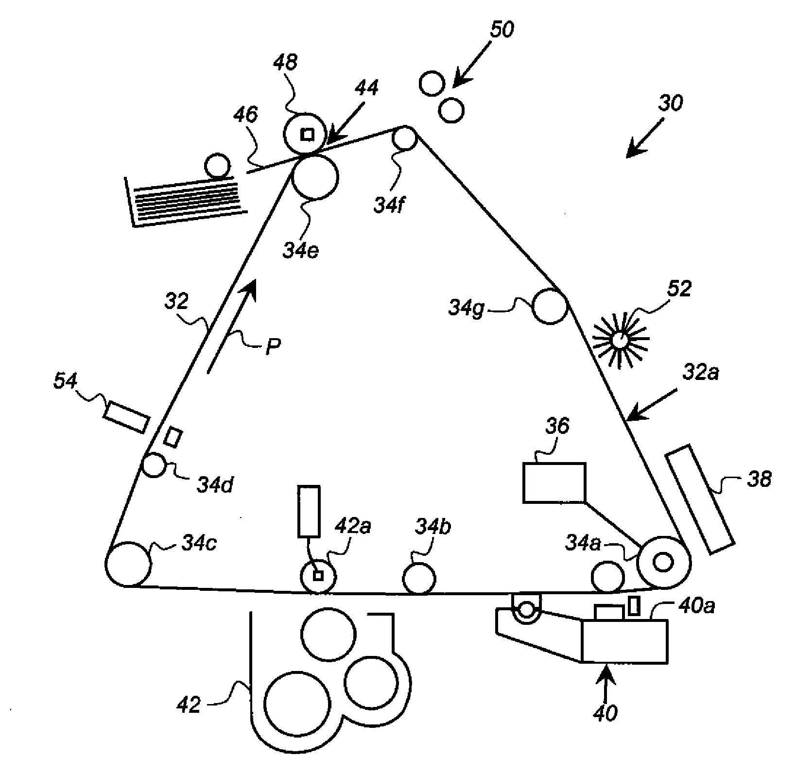
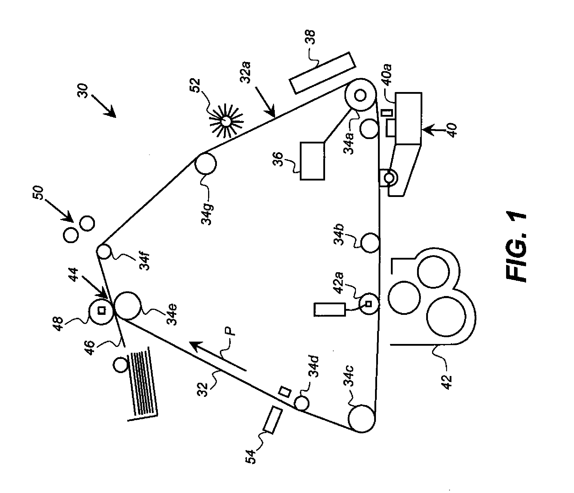
[0053]Examples of inkjet printers are found in U.S. Patent Publication 20110148999, filed Dec. 21, 2009 (drop-on-demand) by O'Leary, et al, U.S. Pat. No. 6,505,921 to Chwalek et al. (continuous), and U.S. Pat. No. 6,508,543 to Hawkins et al. (continuous), the disclosures of which are incorporated herein by reference. Drop-on-demand or continuous inkjet printers can be used with various embodiments. In a drop-on-demand printer, ink is forced out of a nozzle by heat or pressure (e.g., piezoelectric) whenever a location of the receiver member that should receive a drop is in position with respect to the nozzle. In a continuous-inkjet printer, drops are forced out of a nozzle at a regular rate, and drops are deflected so that on...


PUM


Abstract

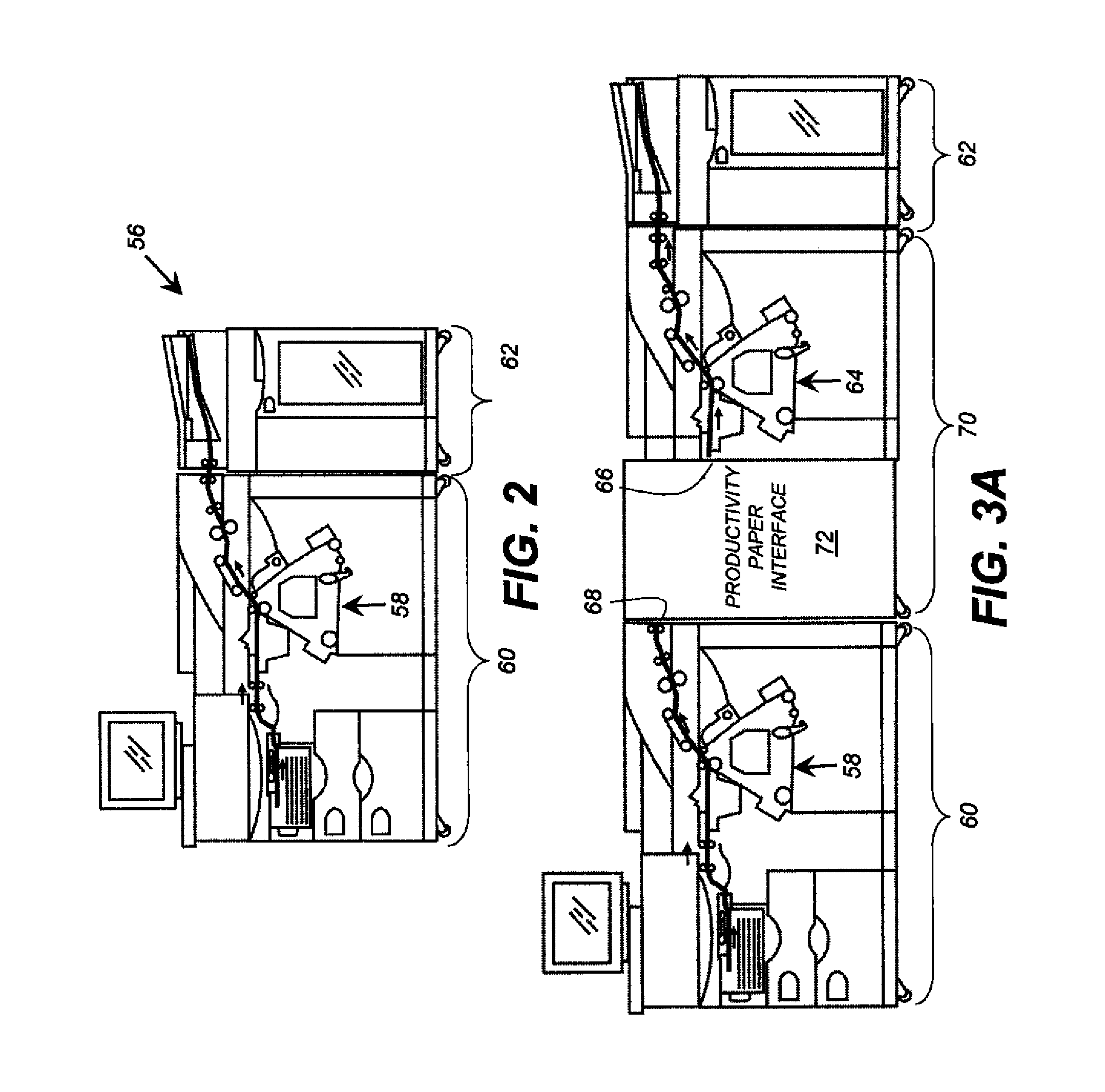
A multi-component duplex print is produced on a receiver. Master print engines and slave print engines synchronized to the masters are arranged along the transport path of the receiver with inverters between them. Each inverter has an inverted travel path and a non-inverted travel path, and a difference of a travel time of the receiver in the inverted travel path of each inverter as compared to a travel time of a receiver in the non-inverted travel path of that inverter is adjusted to be an integral multiple of a period between successive receivers. A received job specification designating a first assigned one of the print engines to print on a first assigned side of the receiver. A controller sets the positions of the inverters so the first assigned side of the moving receiver is the corresponding print side of the first assigned print engine.

Description

FIELD OF THE INVENTION[0001]The claimed invention relates in general to imaging systems having more than one print engine, and more particularly to producing a multi-component duplex print using multiple print engines.BACKGROUND OF THE INVENTION[0002]Electrographic reproduction devices use a latent image charge pattern formed on a uniformly charged charge-retentive or photoconductive member having dielectric characteristics (hereinafter referred to as the dielectric support member). Marking particles (which can contain dyes or pigments) are attracted to the latent image charge pattern to develop the latent image into a developed image on the dielectric support member. A receiver member, such as a sheet of paper, transparency or other medium, is then brought directly, or indirectly via an intermediate transfer member, into contact with the dielectric support member, and an electric field is applied to transfer the marking particle developed image to the receiver member from the diele...

Claims


Application Information

Patent Timeline
IPC IPC(8): G03G13/00
CPCG03G15/238G03G15/6564G03G2215/007G03G2215/00556G03G2215/00599G03G2215/00021
Inventor DOBBERTIN, MICHAEL THOMASYOUNG, TIMOTHY JOHN
Owner EASTMAN KODAK CO
Learn More