Audio encoding apparatus and audio encoding method

a technology of audio encoding and speech, applied in the field of encoding speech apparatus and encoding speech, can solve problems such as difficult to obtain a psychoacoustic model, and achieve the effect of good sound quality

Inactive Publication Date: 2013-01-31
PANASONIC INTELLECTUAL PROPERTY CORP OF AMERICA
View PDF10 Cites 30 Cited by
  • Summary
  • Abstract
  • Description
  • Claims
  • Application Information

AI Technical Summary

Benefits of technology

[0073]According to the present invention, the decoding side can obtain a decoded signal with good sound quality.

Problems solved by technology

Meanwhile, since the linear predictive coding performs linear prediction on an input signal, it is not easy to obtain a psychoacoustic model.

Method used


Image

  • Audio encoding apparatus and audio encoding method
  • Audio encoding apparatus and audio encoding method
  • Audio encoding apparatus and audio encoding method

Examples


embodiment 1

[0106]FIG. 10A illustrates a configuration of speech coding apparatus 1000A according to the present embodiment. FIG. 10B illustrates a configuration of speech decoding apparatus 1000B according to the present embodiment.

[0107]In the present embodiment, a pulse vector coding perceptually weights each spectral coefficient.

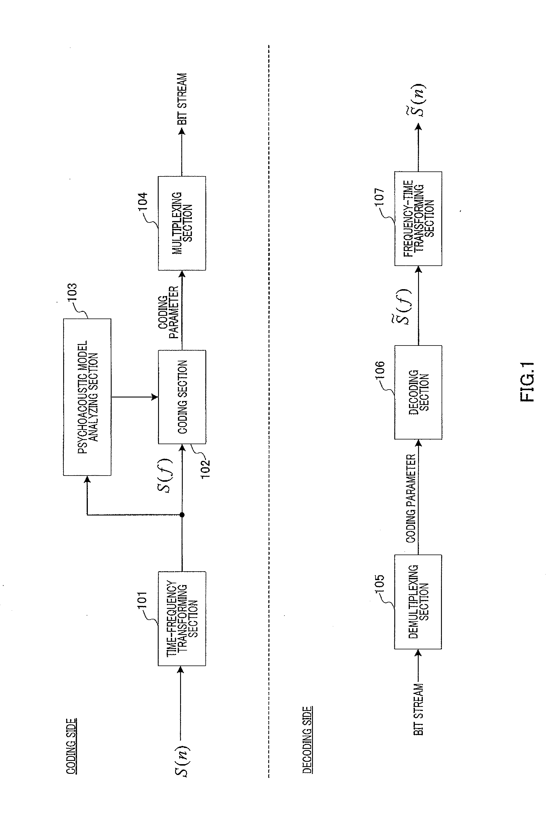
[0108]In speech coding apparatus 1000A (FIG. 10A), time-frequency transforming section 1001 transforms time domain signal S(n) into frequency domain signal S(f) (spectral coefficients), using time-frequency transformation such as discrete Fourier transform (DFT) or modified discrete cosine transform (MDCT).

[0109]Psychoacoustic model analyzing section 1002 determines a masking curve by performing a psychoacoustic model analysis on frequency domain signal S(f).

[0110]Perceptually-weighting section 1003 estimates perceptual importance levels based on the masking curve, and calculates respective weighting coefficients for the spectral coefficients according to the percep...

embodiment 2

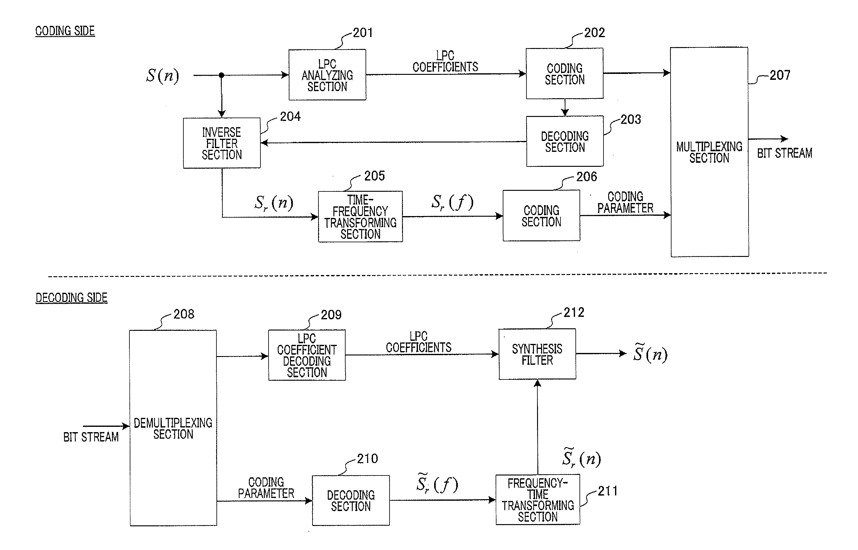
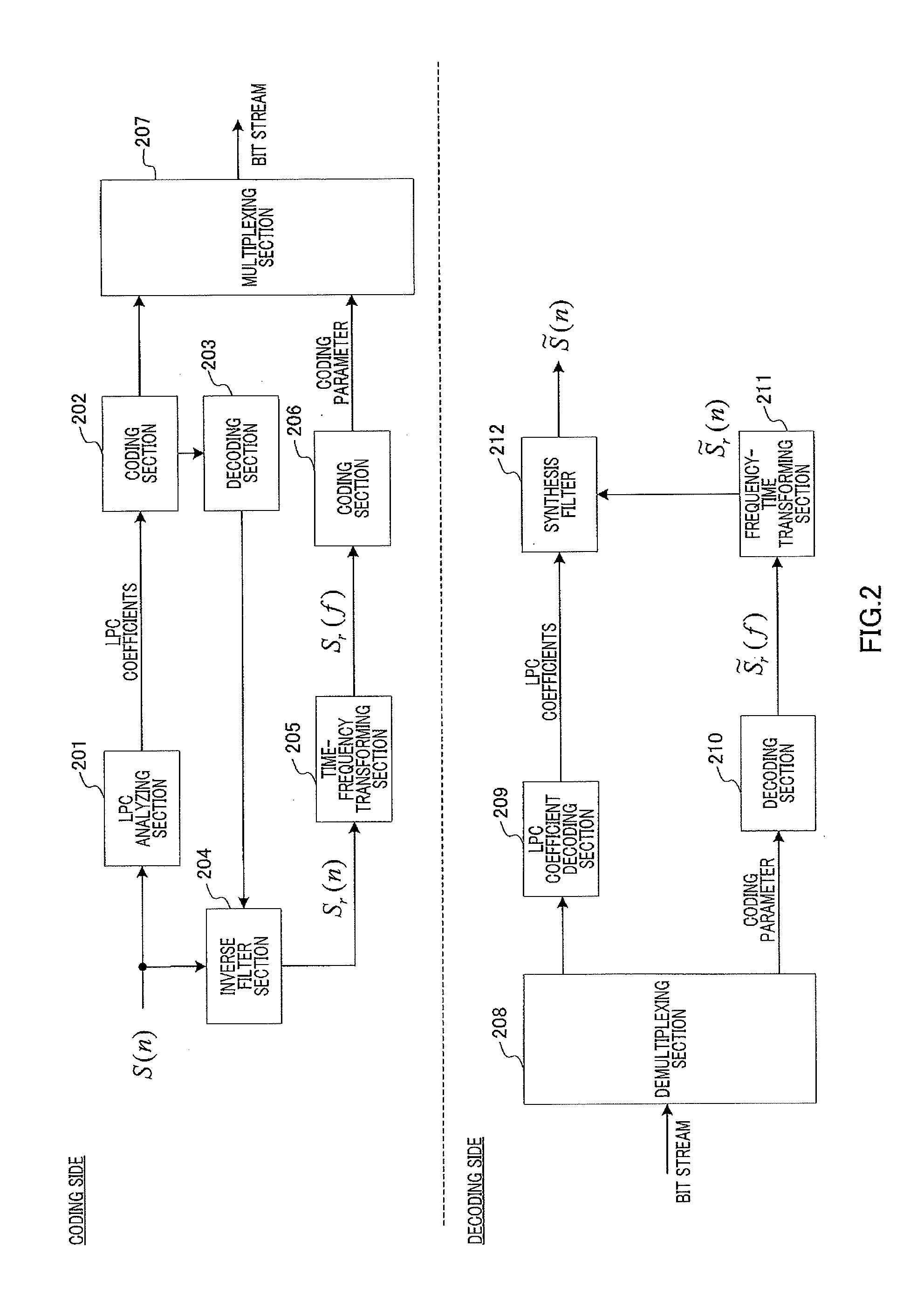
[0127]FIG. 13A illustrates a configuration of speech coding apparatus 1300A according to the present embodiment. FIG. 13B also illustrates a configuration of speech decoding apparatus 1300B according to the present embodiment.

[0128]In the present embodiment, a TCX coding perceptually weights each spectral coefficient.

[0129]In speech coding apparatus 1300A (FIG. 13A), LPC analyzing section 1301 performs LPC analysis on an input signal, so as to use redundancy of a signal in a time domain.

[0130]Coding section 1302 encodes the LPC coefficients from LPC analyzing section 1301.

[0131]Decoding section 1303 decodes the encoded LPC coefficients.

[0132]Inverse filter section 1304 obtains residual (excitation) signal Sr(n) by applying an LPC inverse filter to input signal S(n) using the decoded LPC coefficients from decoding section 1303.

[0133]Time-frequency transforming section 1305 transforms residual signal Sr(n) into frequency domain signal Sr(f) (spectral coefficients) using time-frequency...

embodiment 3

[0151]FIG. 16A illustrates a configuration of speech coding apparatus 1600A according to the present embodiment. FIG. 16B also illustrates a configuration of speech decoding apparatus 1600B according to the present embodiment.

[0152]In the present embodiment, layer coding (scalable coding), in which a lower layer adopts a CELP coding and a higher layer adopts a transform coding, perceptually weights each spectral coefficient. In the following explanation, although the layer coding including two layers of the lower layer and the higher layer will be explained as an example, it is possible to apply the present invention to the layer coding including three layers or more.

[0153]In speech coding apparatus 1600A (FIG. 16A), CELP coding section 1601 performs a CELP coding on an input signal so as to use redundancy of a signal in a time domain.

[0154]CELP decoding section 1602 generates synthesized signal Ssyn(n) using the CELP parameter.

[0155]By subtracting the synthesized signal from the in...


PUM


Abstract

An audio encoding apparatus that allows a decoded signal exhibiting an excellent sound quality to be obtained on a decoding side. In the audio encoding apparatus (1000A), a time-frequency transform unit (1001) uses a time-frequency transform, such as a discrete Fourier transform (DFT) or a modified discrete cosine transform (MDCT), to transform a time domain signal (S(n)) to a frequency domain signal (spectrum factor) (S(f)). A psychoacoustic model analyzing unit (1002) performs a psychoacoustic model analysis of the frequency domain signal (S(f)), thereby obtaining a masking curve. An acoustic sense weighting unit (1003) estimates, based on the masking curve, an importance degree of acoustic sense, and determines and applies the weighting factors of respective spectrum factors to the respective spectrum factors. An encoding unit (1004) encodes the frequency domain signal (S(f)) as weighted in terms of the acoustic sense. A multiplexing unit (1005) multiplexes and transmits the encoded parameters.

Description

TECHNICAL FIELD [0001]The present invention relates to an encoding speech apparatus and an encoding speech method.BACKGROUND ART [0002]Speech coding techniques are categorized into mainly two coding techniques, i.e., transform coding and linear predictive coding.[0003]The transform coding transforms signals from a time domain into a spectral domain and then encodes spectral coefficients using a discrete Fourier transform (DFT) or a modified discrete cosine transform (MDCT), for example. The coding process generally involves calculating perceptual importance levels of the spectral coefficients using a psychoacoustic model and then encoding the spectral coefficients according to each perceptual importance level. Some common transform coding techniques include MPEG MP3, MPEG AAC, and Dolby AC3. The transform coding is effective for music signals and general speech signals.[0004]FIG. 1 illustrates a configuration of the transform coding.[0005]In the coding side of FIG. 1, time-frequency...

Claims


Application Information

Patent Timeline
Patent Type & Authority Applications(United States)
IPC IPC(8): G10L21/00G10L19/02G10L19/032G10L19/24
CPCG10L19/0212G10L19/24G10L19/12
Inventor LIU, ZONGXIAN
Owner PANASONIC INTELLECTUAL PROPERTY CORP OF AMERICA
Why Eureka
Try Eureka