Crane control systems and methods

a control system and crane technology, applied in the field of crane control systems and methods, can solve the problems of response delay, natural tendency of payload to oscillate, and detriment to efficient operation, and achieve the effects of dampening payload oscillation, simplifying crane system operation, and dampening payload oscillation

Active Publication Date: 2013-02-07
GEORGIA TECH RES CORP
View PDF3 Cites 14 Cited by
  • Summary
  • Abstract
  • Description
  • Claims
  • Application Information

AI Technical Summary

Benefits of technology

[0007]The present invention relates to crane control systems and methods. In a crane system comprising a crane trolley and a supporting device for carrying a payload, an exemplary embodiment of the present invention provides a crane control system useful for simplifying the crane system operation and for maintaining a safe distance between the payload and a specific location (most typically the location of a locator device, which is in the hand of the operator), the locator device for manipulating at least one of the position and speed of the supporting device. The crane control system is also useful in dampening payload oscillations when the crane trolley is either accelerated or decelerated. An exemplary crane control system comprises a real-time position-location module, an on-off controller module, and an input shaper module. The real-time position-location module generates a position signal indicative of a vector between an element of the crane system and the locator device used to manipulate at least one of the position and speed of the crane trolley. In an exemplary embodiment, the element of the crane system is the crane trolley, and the position signal is indicative of the horizontal planar distance between the crane trolley and the locator device. In another exemplary embodiment, the locator device is portable. The on-off controller module maps the position signal to a velocity command signal, wherein the velocity command signal comprises instructions for the crane trolley to move the supporting device in a vector relative to the locator device in at least a first velocity only if the magnitude of the vector between the element of the crane system and the locator device is greater than a cut-off threshold, wherein the at least a first velocity is a substantially constant velocity. The input shaper module manipulates the velocity command signal mapped by the on-off controller module to dampen payload oscillations when the crane trolley is accelerated or decelerated.

Problems solved by technology

Unfortunately, one inherent property of conventional crane assemblies that is detrimental to efficient operation is the natural tendency for the payload to oscillate like a pendulum, a double-pendulum, or with hoist-related oscillatory dynamics.
Because crane operators can only drive the overhead crane trolley—not the payload—there is a response delay from the time the trolley moves to the time the payload moves.
This delay results in oscillations in the payload as the trolley slows down (suddenly) or stops moving.
The oscillating payload can be very dangerous to the payload, as it may collide with surroundings, or workers in the area.
In conventional crane control systems, this delay causes cranes that contain rotational joints an especially challenging control problem because their nonlinear dynamics create additional complexities.
Unfortunately, in addition to facing the challenges of controlling large amplitude, lightly-damped payload swing, operators of conventional crane control systems must also master non-intuitive machine interfaces, which require extensive training.
Therefore, expert crane operators typically require years of experience and training.

Method used


Image

  • Crane control systems and methods
  • Crane control systems and methods
  • Crane control systems and methods

Examples


Embodiment Construction

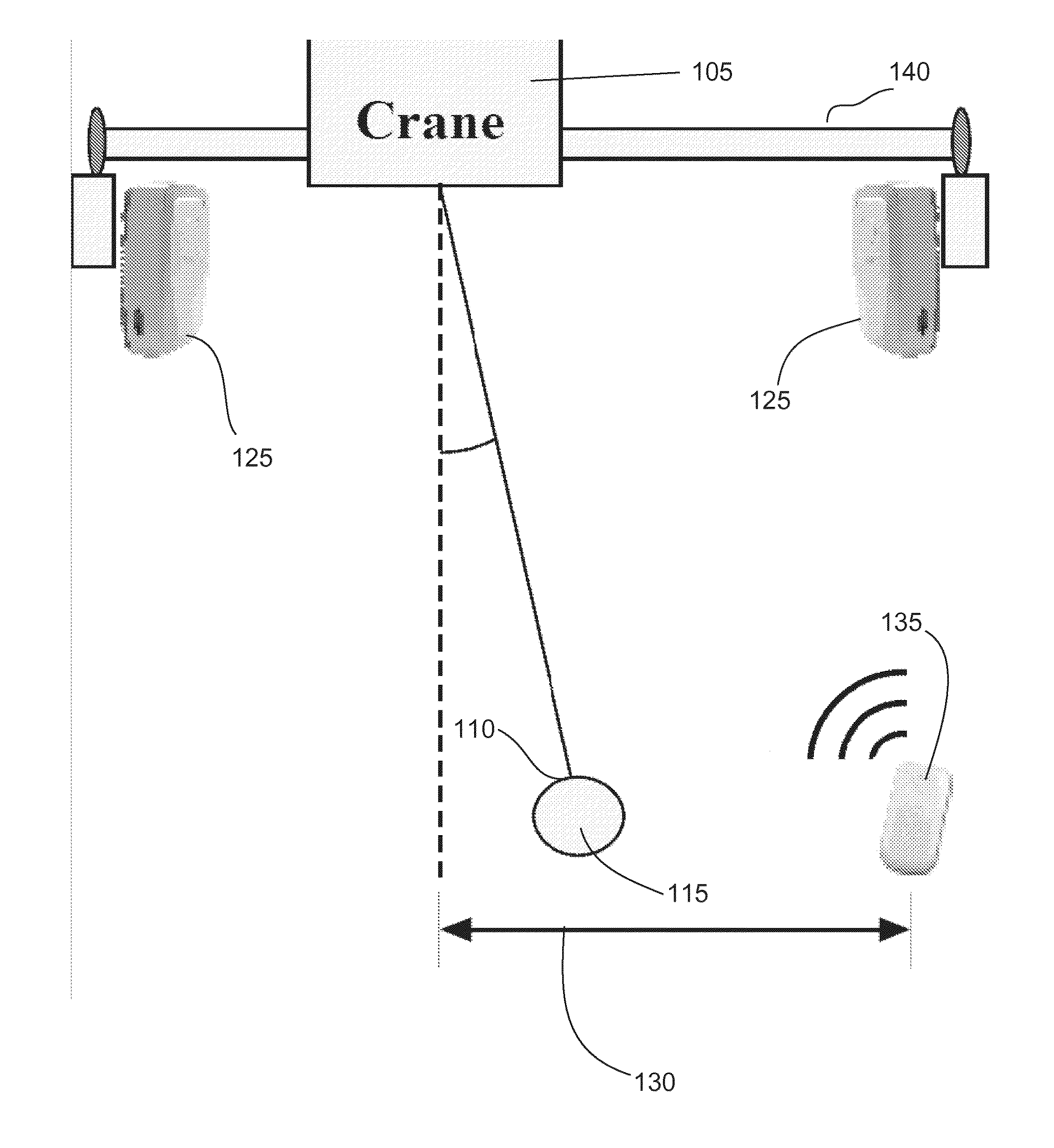
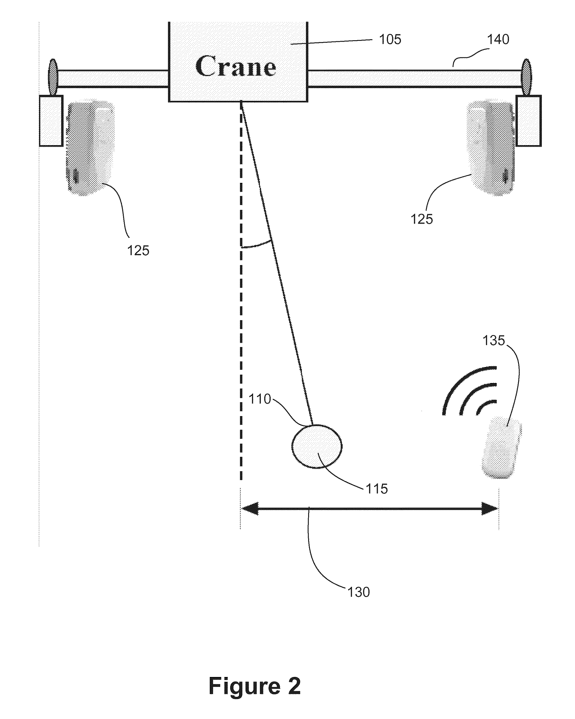
[0032]To facilitate an understanding of the principles and features of the present invention, various illustrative embodiments are explained below. In particular, the invention is described in the context of being crane control systems and methods. Embodiments of the present invention may be applied to systems or methods for controlling the movement of elements of a crane system via a locator device. Embodiments of the invention, however, are not limited to only use in systems and methods for controlling a crane system. As those of ordinary skill in the art would understand, embodiments of the invention can be used by other systems or methods for controlling other systems via a locator device using, for example, RF signals, SONAR, RADAR, GPS, and the like.

[0033]The components described hereinafter as making up various elements of the invention are intended to be illustrative and not restrictive. Many suitable components or steps that would perform the same or similar functions as th...


PUM


Abstract

The various embodiments of the present disclosure relate generally to crane control systems. An exemplary embodiment of the present invention provides a crane control system comprising a real-time position-location module, an on-off controller module, and an input-shaper module. The real-time position-location module generates a position signal indicative of the distance between crane trolley and a desired location of safety. The on-off controller module maps the position signal to a velocity command signal, wherein the velocity command signal comprises instructions for the crane trolley to move in a vector relative to the desired location in at least a first velocity only if the distance between the crane trolley and the desired location is greater than a cut-off threshold 150. The at least a first velocity is a substantially constant. The input shaper module manipulates the velocity command signal mapped by the on-off controller module to dampen payload oscillations.

Description

CROSS-REFERENCE TO RELATED APPLICATIONS[0001]This application claims the benefit of U.S. Provisional Application Ser. No. 61 / 327,337, filed Apr. 23, 2010, and U.S. Provisional Application Ser. No. 61 / 358,164, filed Jun. 24, 2010, both of which are incorporated herein by reference in their entireties as if fully set forth below.TECHNICAL FIELD OF THE INVENTION[0002]The various embodiments of the present disclosure relate generally to control systems and methods. More particularly, the various embodiments of the present invention are directed to crane control systems and methods.BACKGROUND OF THE INVENTION[0003]Cranes play a key role in maintaining the economic vitality of modern-day industry. Their importance can be seen at shipyards, construction sites, warehouses, and in a wide variety of material-handling applications. The effectiveness of crane manipulation is an important contributor to industrial productivity, low production costs, and worker safety. Unfortunately, one inherent...

Claims


Application Information

Patent Timeline
Patent Type & Authority Applications(United States)
IPC IPC(8): B66C13/18B66C13/06
CPCB66C13/40B66C13/063
Inventor SINGHOSE, WILLIAMPENG, CHEN CHIH
Owner GEORGIA TECH RES CORP
Why Eureka
Try Eureka