
Laryngoscope disinfector

Active Publication Date: 2013-02-07
RIFE ROBERT
View PDF0 Cites 9 Cited by
  • Summary
  • Abstract
  • Description
  • Claims
  • Application Information

AI Technical Summary

Benefits of technology

The present invention is a device that uses ultraviolet light to disinfect a laryngoscope. It has a drawer that can hold the laryngoscope and expose all surfaces to the light for disinfection. The blades can be positioned horizontally or vertically for this purpose. The device also has a position for the laryngoscope handles. The technical effect of this invention is to provide a convenient and effective way to disinfect laryngoscopes between uses.

Problems solved by technology

The use of chemical agents for disinfecting is problematic.

Method used


Image

  • Laryngoscope disinfector
  • Laryngoscope disinfector
  • Laryngoscope disinfector

Examples


Embodiment Construction

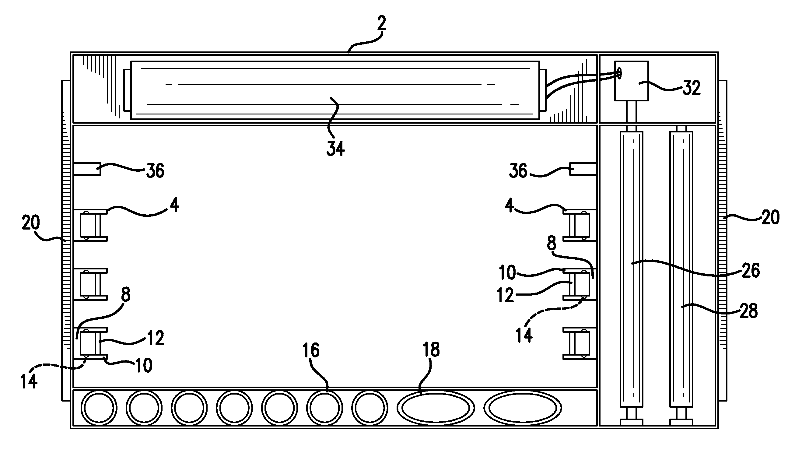
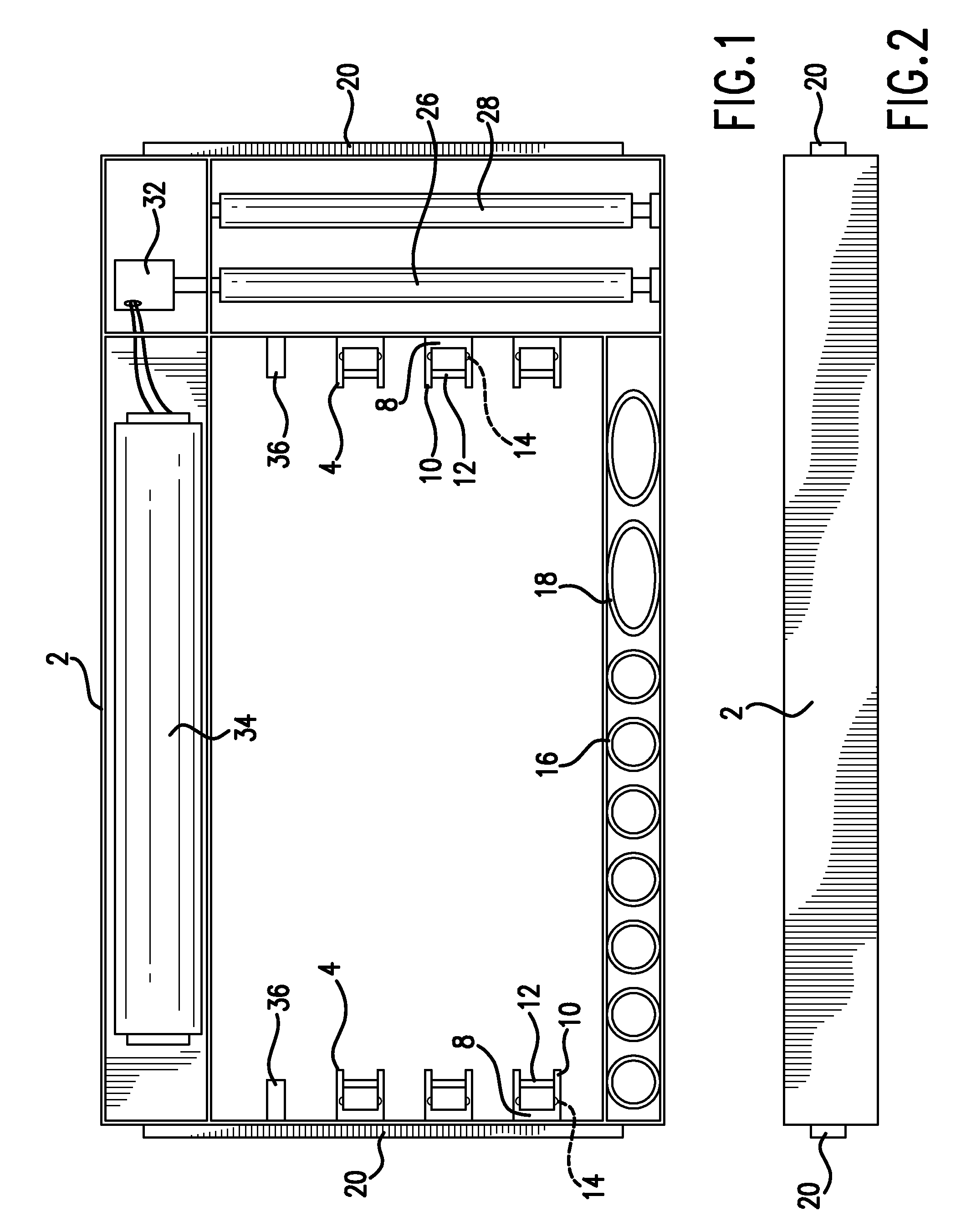
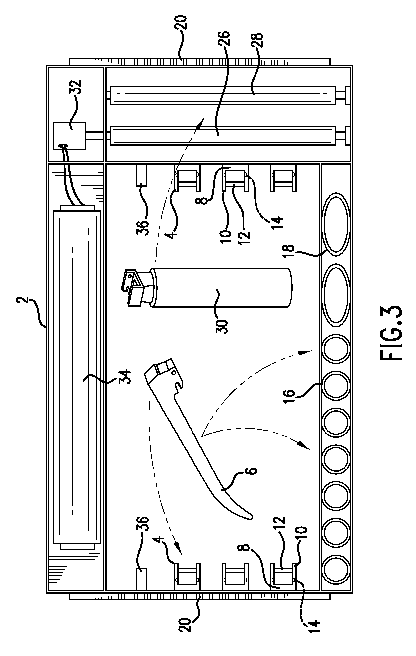
[0014]Turning now to the drawing figures, a preferred embodiment of the invention is formed as a drawer 2. FIG. 1. The drawer has a plurality of sides that form an annular boundary of the drawer. In a preferred embodiment, the drawer is generally rectangular, and has at least four (4) sides that form the annular drawer. The top and bottom of the drawer are open, that is, there are no barriers to obstruct the transmission of the ultraviolet light, so that ultraviolet light is directed through the drawer from top to bottom or bottom to top, and preferably, in both directions. FIG. 5. Alternatively, the drawer may be formed with a top and / or a bottom; however, the top and / or bottom must be formed of a material that is substantially transparent to ultraviolet radiation and will permit ultraviolet radiation to pass through the material.

[0015]Sides of the drawer may have mounting brackets 4 extending there from as shown in the embodiments of the drawing figures. A plurality of brackets is...


PUM


Abstract

A laryngoscope disinfector characterized by a drawer that provides positioning for laryngoscopes in the drawer so that all surfaces of the laryngoscopes are exposed to ultraviolet radiation. The drawer provides for the laryngoscope blades to be positioned generally horizontally and generally vertically for disinfection of the blades. The drawer also provides, in some embodiments, positioning for the laryngoscope handles.

Description

FIELD OF THE INVENTION[0001]This invention relates to medical devices generally, and is more specifically directed to an ultraviolet disinfector for laryngoscopes.BACKGROUND OF THE INVENTION[0002]Laryngoscopes in common use are characterized by a handle, with a blade extending from the handle. In most embodiments, the blade is curved, and extends at generally a right angle from the handle. The handle is usually held in a generally vertical orientation. The handle may contain a battery for powering a light source that is present in the laryngoscope blade. The handle may provide light by means of a fiber optic light source. In more sophisticated embodiments, the handle and blade may provide video imaging which appears on a remote monitor.[0003]For laryngoscopes as contemplated by the present invention, the blade may be separated from the handle. Since the blade is inserted through the patient's mouth, it is imperative that the blade is disinfected, and even sterilized, prior to reuse....

Claims


Application Information

Patent Timeline
IPC IPC(8): A61L2/10
CPCA61L2/10A61L2202/24A61L2202/122
Inventor RIFE, ROBERT
Owner RIFE ROBERT
Learn More