Continuous current rod antenna
a current rod and continuous technology, applied in the direction of antennas, antenna details, protective materials, etc., can solve the problems of affecting the bandwidth and/or efficiency of optimizing one requirement, affecting the other requirements, and applications such as airborne platforms cannot afford even a meter of added space, etc., to achieve stable radiation impedance, lower profile packaging, and higher gain
Active Publication Date: 2013-02-14
RAYTHEON CO
View PDF15 Cites 2 Cited by
- Summary
- Abstract
- Description
- Claims
- Application Information
AI Technical Summary
Benefits of technology
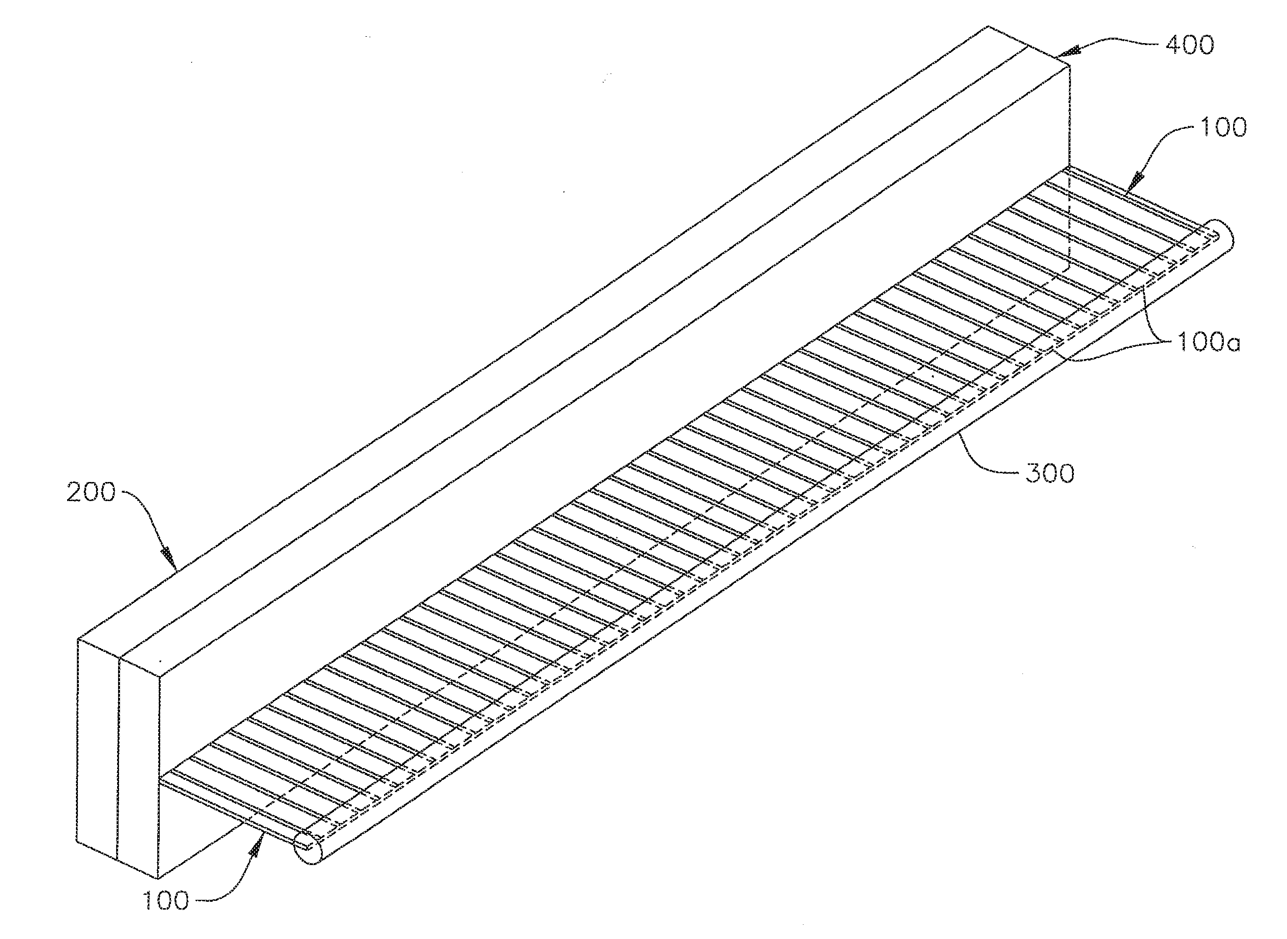
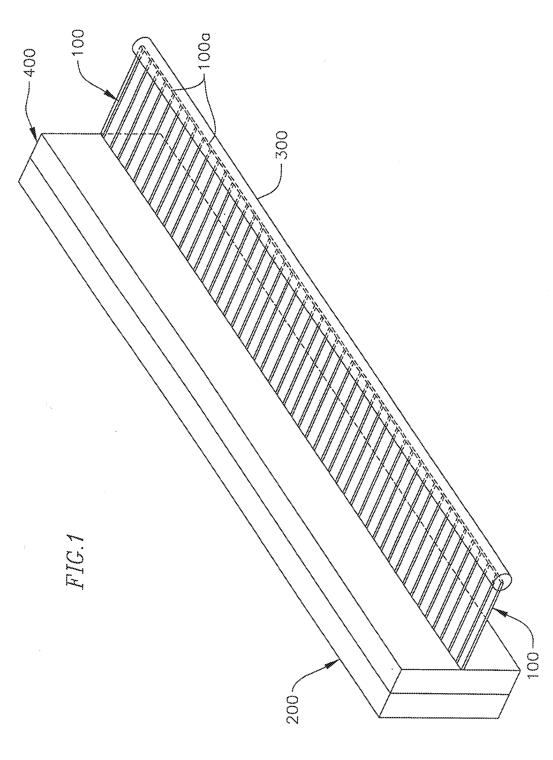
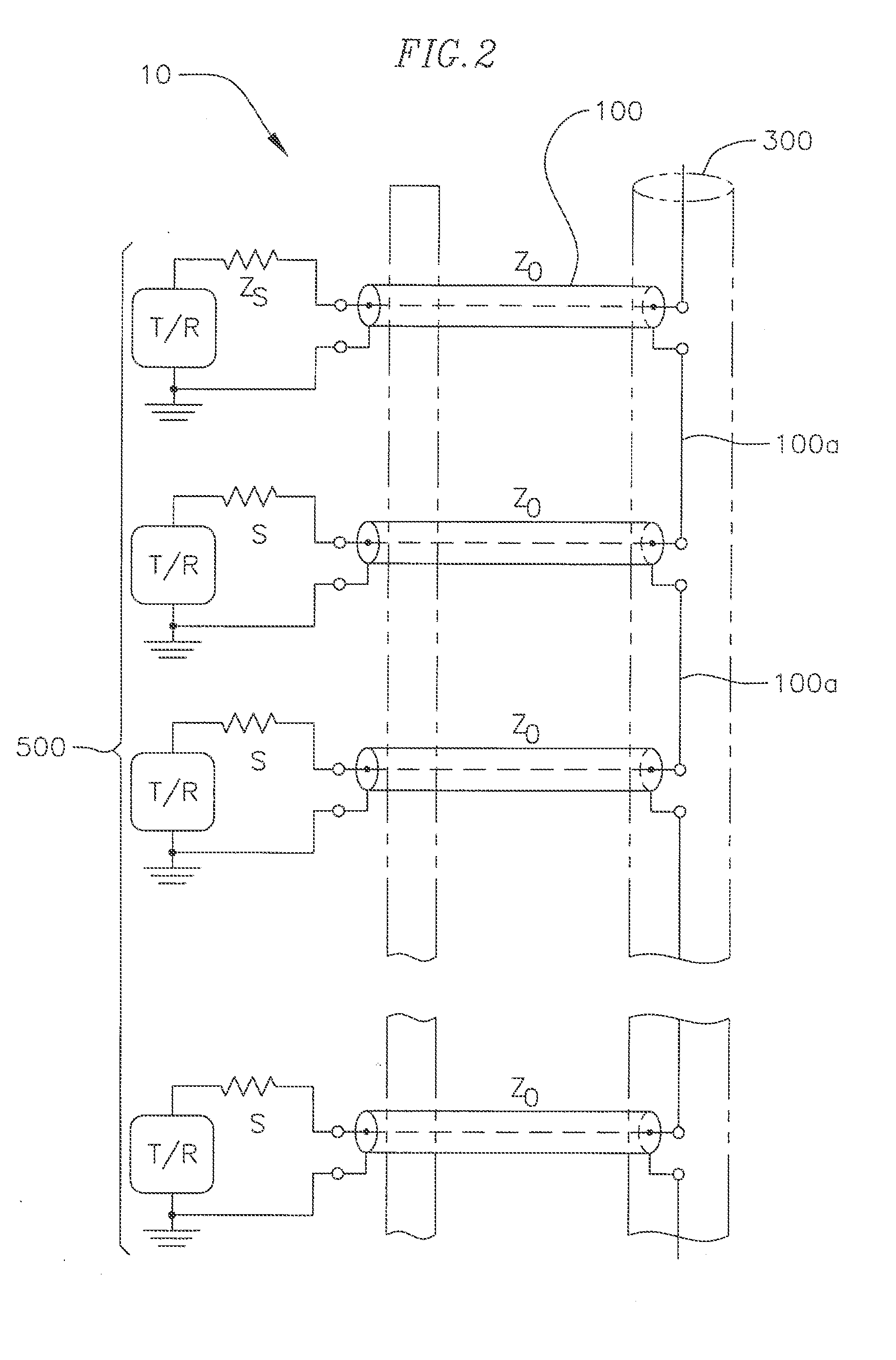
[0011]Aspects of embodiments according to the present invention are directed toward a novel Continuous Current Rod Antenna that may be fabricated by coupling an array of collinear antenna elements in close proximity to a conductive backplane that is optionally covered with an RF absorber, or meta material. The Continuous Current Rod Antenna has extremely tight lattice which stabilizes the radiation impedance and allows dense T/R modules packaging. A current filament is excited by connecting parall
Problems solved by technology
However, placing a collinear antenna array in close proximity to its support structures typically results in a tradeoff between bandwidth and/or efficiency.
Requirements for antenna arrays to be both compact and wideband generally oppose one another so that optimizing one requirement often negatively affects the other requirements.
This is a particular problem for UHF and VHF antenna arrays in which wavelengths range from meters to tens of meters.
Some applications such as an airborne platform cannot afford even a meter of added space to house a wideband antenna array on the vehicle or in an external pod.
Prior antenna designs have been developed and have failed to meet the desired requirements, which are to be low profile, have a wide bandwidth, and have the ability to support frequency scan as required for a phased array sensor system.
In addition, end fed arrays such as those disclosed in Al
Method used
View moreImage
Smart ImageViewing Examples
Examples
 PUM
 Abstract
A Continuous Current Rod Antenna that may be positioned in close proximity to a conductive backplane and has extremely tight lattices which stabilize the radiation impedance and allows dense UR modules packaging. The Continuous Current Rod Antenna offers lower profile packaging, with higher gain over larger bandwidths than other collinear array techniques.
Description
BACKGROUND[0001]1. Field[0002]Aspects of the present invention relate to antenna arrays, and particularly, collinear antenna arrays.[0003]2. Description of Related Art[0004]Collinear antenna arrays have many applications and are often used for aerodynamic applications. An exemplary collinear antenna array includes an array of dipole antennas mounted in such a manner that the corresponding antenna filaments of each antenna are parallel and collinear along a common line or axis. A collinear antenna array may be mounted vertically or horizontally in order to increase overall gain and directivity in the desired direction. However, placing a collinear antenna array in close proximity to its support structures typically results in a tradeoff between bandwidth and / or efficiency. Requirements for antenna arrays to be both compact and wideband generally oppose one another so that optimizing one requirement often negatively affects the other requirements. This is a particular problem for UHF ...
Claims
Login to View More Application Information
Patent Timeline
 IPC IPC(8): H01Q1/00
CPCH01Q1/40H01Q21/10H01Q19/108
Inventor LIVINGSTON, STANLEY W.
Owner RAYTHEON CO
Features
- R&D
- Intellectual Property
- Life Sciences
- Materials
- Tech Scout
- Unparalleled Data Quality
- Higher Quality Content
- 60% Fewer Hallucinations
Learn More Browse by: Latest US Patents, China's latest patents, Technical Efficacy Thesaurus, Application Domain, Technology Topic, Popular Technical Reports.
© 2025 PatSnap. All rights reserved.Legal|Privacy policy|Modern Slavery Act Transparency Statement|Sitemap|About US| Contact US: help@patsnap.com


