
Automated control system and supervisor scheduler usable with same

a technology of automatic control system and supervisor scheduler, which is applied in the direction of programme control, electric controller, total factory control, etc., can solve the problems of critical defect, lack of flexibility, and users' inability to find a universal control system that fits most of the controllers and devices in the mark

Inactive Publication Date: 2013-02-14
ZHANG SHUO +3
View PDF4 Cites 55 Cited by
  • Summary
  • Abstract
  • Description
  • Claims
  • Application Information

AI Technical Summary

Benefits of technology

The invention is about a new way to control different systems with one software. This allows users to edit their own automation processes and have them work on different systems. This is made possible through a computerized method that allows for easy control and customization.

Problems solved by technology

Many factory PLC-type control systems are available in the market but nearly all of them have a critical defect, lack of flexibility.
Such changes are typically the province of specialists, who are frequently engineers and electricians, and are not commonly achievable by routine factory workers.
Users cannot find a universal control system to fit most of the controllers and devices in the market.
Another issue is that a controller is designed for a particular GUI and automation process.
This situation is fraught with difficulty.
However, PAC's lack flexibility and simplicity.
One issue is that user must learn how to write such programs; to some degree, it is similar to Ladder Logic.
Another issue is the control system is always designed for a specific controller, so these programs are very difficult to run on other controllers.
Even if the problems mentioned above are overcome, it is often difficult for a chemical or other production facility to properly schedule and supervise a particular production run, or even more significantly, numerous production runs for a variety of customers.
Often, it is difficult for factory personnel or even engineers to conceive of the manner in which such control systems should be designed and set up.

Method used

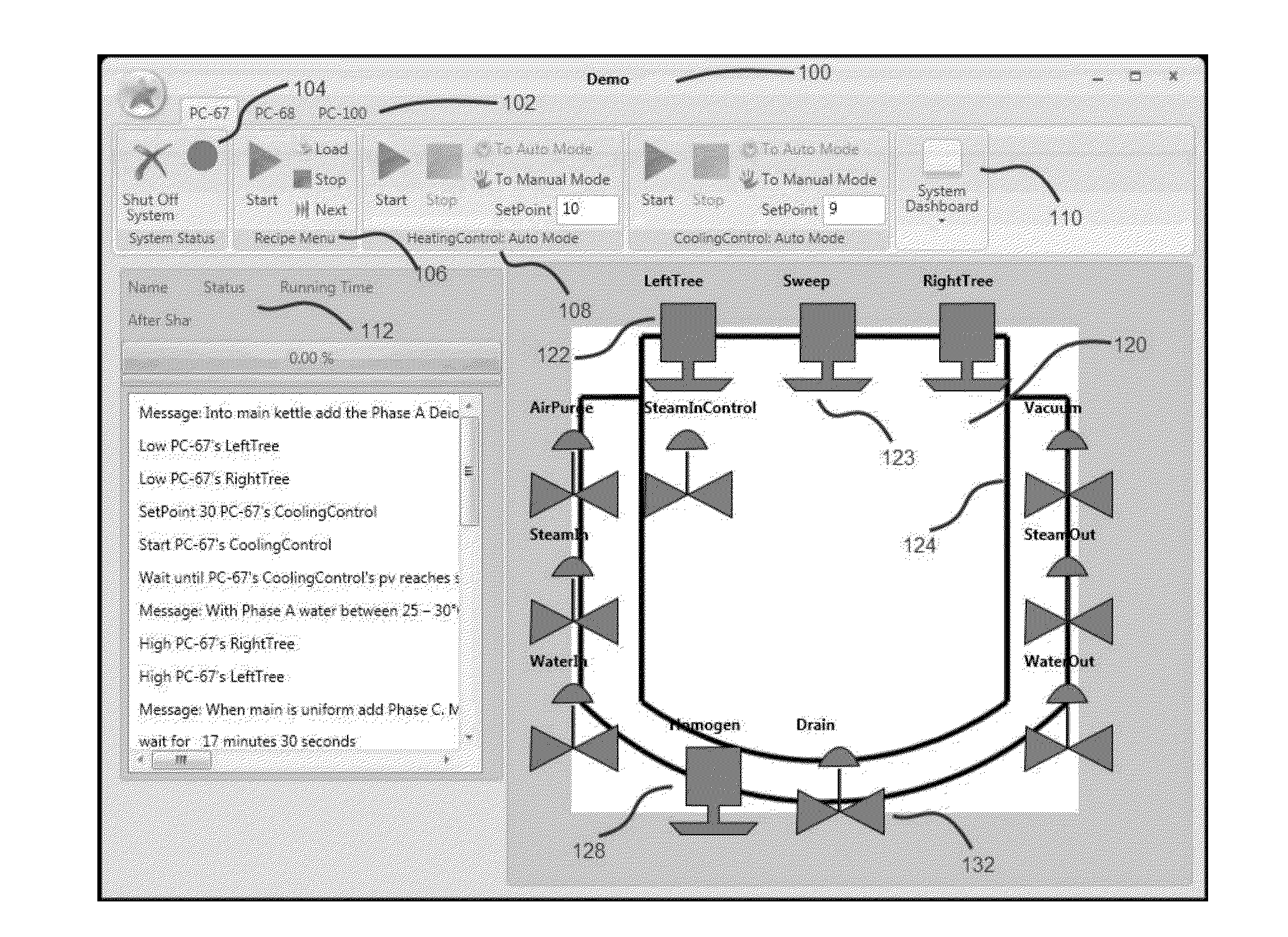
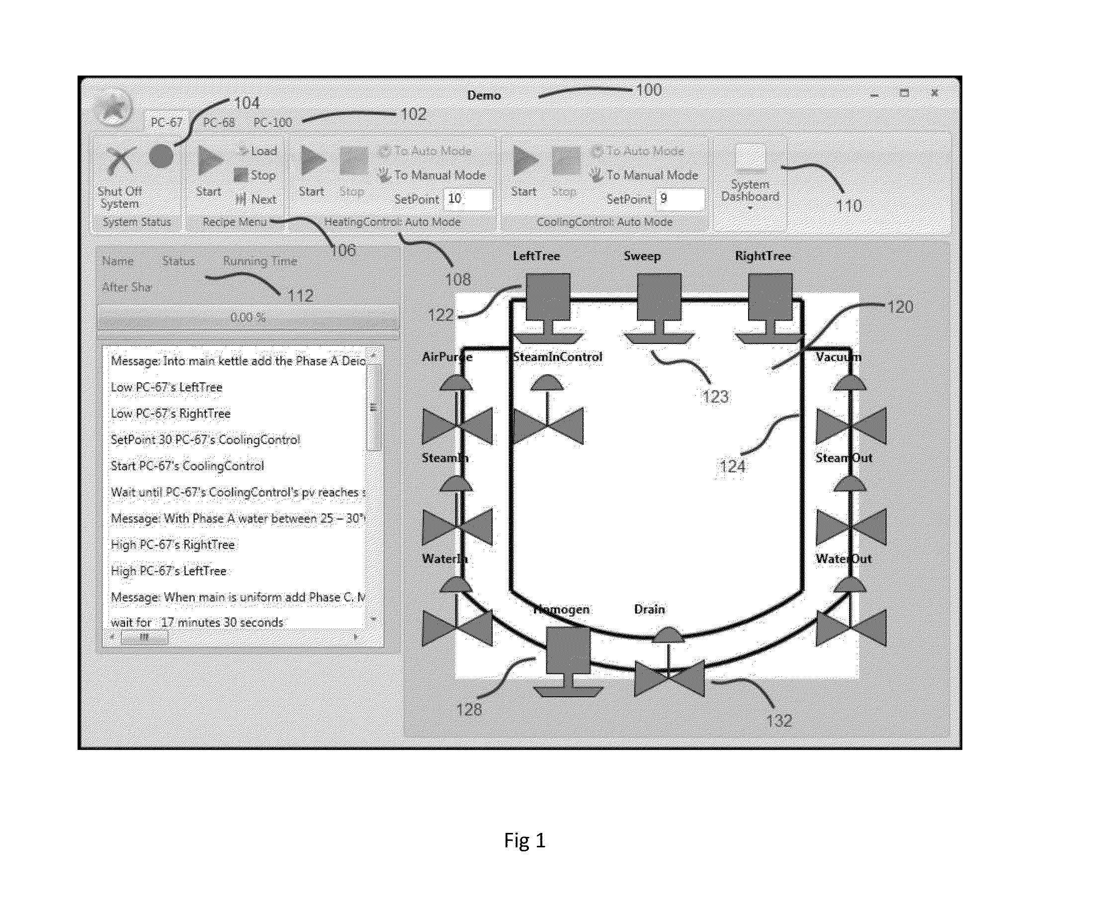
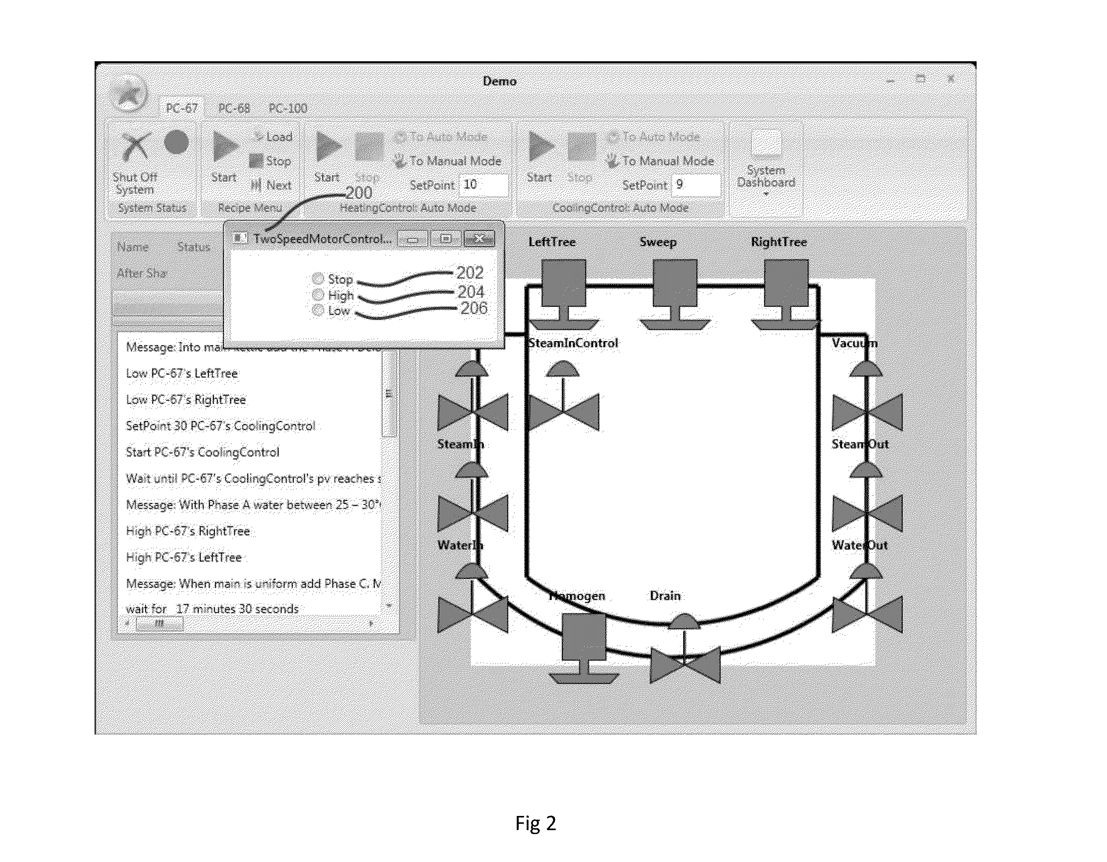

Image

  • Automated control system and supervisor scheduler usable with same
  • Automated control system and supervisor scheduler usable with same
  • Automated control system and supervisor scheduler usable with same

Examples


Embodiment Construction

[0076]Although the present invention will be described with reference to the embodiments shown in the drawings, it should be understood that the present invention can be embodied in many alternate forms of embodiments. In addition, any suitable size types of elements or materials could be used.

[0077]The description below is divided into five sections. The first section, entitled Overview, presents aspects of the control system during routine use. The second section, entitled, Architecture, presents detailed information about the processing and computations that underlie the inventions. The third section, entitled Implementation, presents detailed examples of several embodiments of the subject matter mentioned in the Principles section. The fourth section, entitled applications, presents disparate examples of the utility of the devices enabled by the methods of the application section. The fifth section, entitled Supervisor Scheduler, presents methods of conveniently scheduling and o...


PUM


Abstract

A computerized method of offering a comprehensive control system for varied kinds of manufactures, including: providing a computer graphical user interface having the static model of hardware systems, information and status of the control system and context of the automation procedure commands; providing a hardware database containing 1) port database including all ports of a controller connecting to devices, 2) a device database including information, operation methods, events of all devices connected to the controller, 3) a system database including information and configuration of all systems that controller controls; providing a dictionary containing word pairs that define operations and status of every device; providing a background worker responsible for refreshing data from port database. Computer systems configured to perform the method.

Description

[0001]This application is a continuation-in-part of application Ser. No. 13 / 007,512, filed on Jan. 14, 2011, which is a continuation-in-part of application Ser. No. 12 / 791,778 filed on Jun. 1, 2010, which is a continuation of application Ser. No. 12 / 580,245 filed on Oct. 15, 2009, now abandoned, which in turn claims priority under 35 U.S.C. 119(e) from provisional application Ser. Nos. 61 / 105,719 and 61 / 105,778 which were both filed on Oct. 15, 2008. All of these documents are incorporated herein by reference, in their entireties, for all purposes.BACKGROUND[0002]1. Field of the Invention[0003]The present invention relates to industrial control apparatus and methods and to the manner in which such apparatus and methods may be utilized for more efficient industrial production. More specifically, the present invention relates to graphical user interfaces and computerized systems for industrial control and manufacture. The invention also relates to those apparatus and methods that may ...

Claims


Application Information

Patent Timeline
IPC IPC(8): G05B15/02
CPCG05B19/056G05B2219/31334Y02P90/02
Inventor ZHANG, SHUOINTURI, CHANDRA SEKHARLABELLO, CHRISTOPHERGANZ, ALAN M.
Owner ZHANG SHUO
Learn More