Mechanical locking system for floor panels

a technology of locking system and floor panel, which is applied in the direction of sheet joining, building components, fastening means, etc., can solve the problems of high material content, complicated snap connection, and poor material content, and achieve cost-effective effects

Active Publication Date: 2013-02-21
CERALOC INNOVATION AB
View PDF11 Cites 191 Cited by
  • Summary
  • Abstract
  • Description
  • Claims
  • Application Information

AI Technical Summary

Benefits of technology

[0021]An overall objective of embodiments of the present disclosure is to provide an improved and more cost efficient locking system for primarily rectangular floor pan...

Problems solved by technology

Such a snap connection is complicated since a hammer and a tapping block has to be used to overcome the friction between the long edges and to bend the strip during the snapping action.
Such locking systems suffer from several disadvantages.
The material content is high due to the design and only limited material savings may be reached.
This fixing of the strip to the edge is rather complicated and slow.
The short side production speed is howev...

Method used


Image

  • Mechanical locking system for floor panels
  • Mechanical locking system for floor panels
  • Mechanical locking system for floor panels

Examples


Embodiment Construction

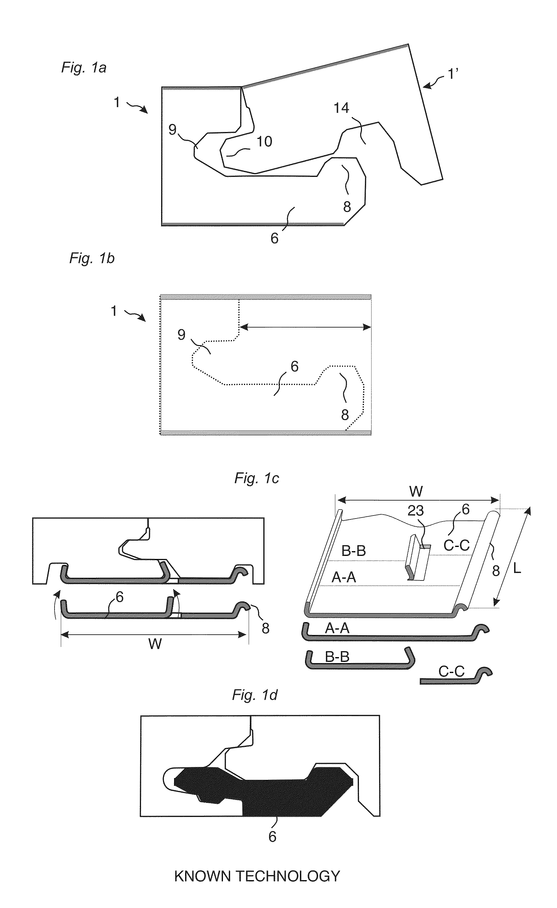
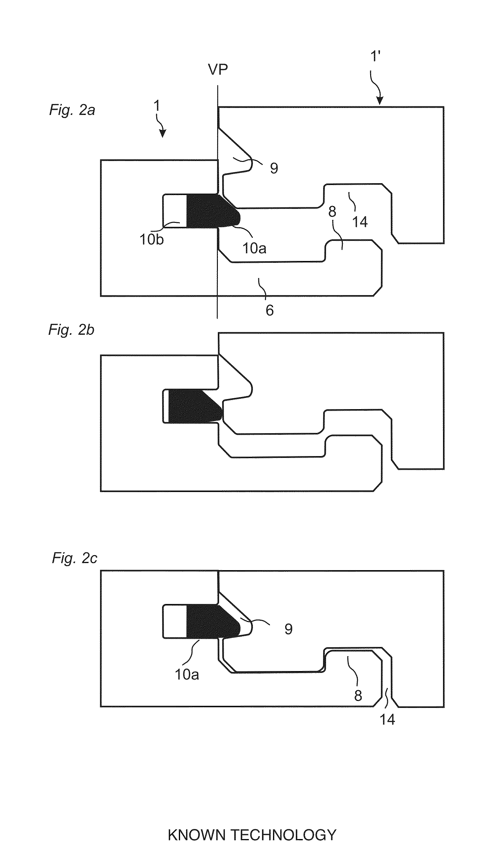
[0069]To facilitate understanding, several locking systems in the figures are shown schematically. It should be emphasised that improved or different functions can be achieved using combinations of the embodiments.

[0070]All embodiments may be used separately or in combinations. Angles, dimensions, rounded parts, spaces between surfaces etc. are only examples and may be adjusted within the basic principles of the disclosure.

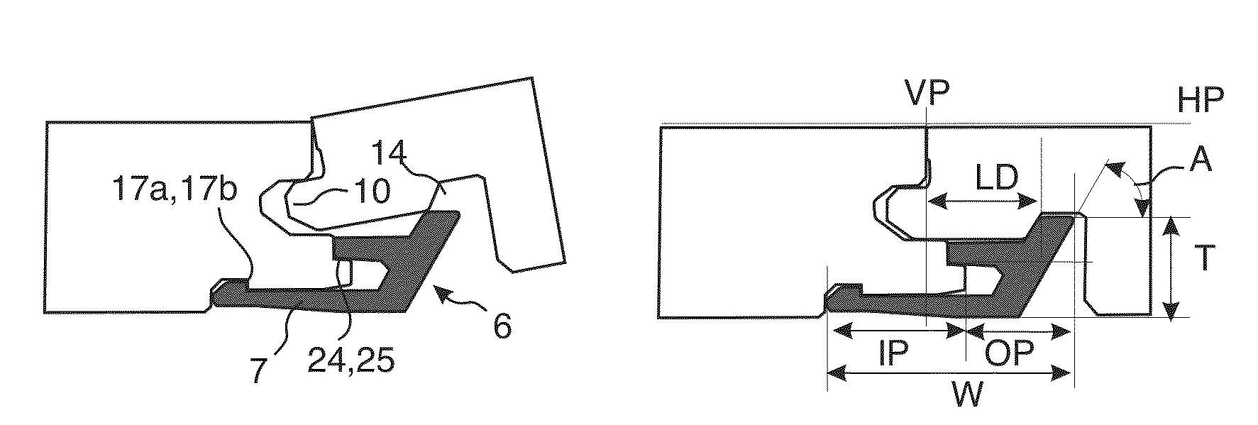
[0071]FIGS. 4a-4d show a locking system according to embodiments of the disclosure that may be connected with angling. FIG. 4a shows a strip part 6 comprising a strip body 7 with a fixing element 16 at an outer part, an upwardly extending locking element 8 at an opposite and outer part of the strip body and a locking protrusion 19 that preferably extends essentially horizontally towards the fixing element. The upper part of the locking element 8 comprises an upper guiding surface 22 and the strip body 7 comprises a lower guiding surface that facilitates the fixati...


PUM

PropertyMeasurementUnit
Lengthaaaaaaaaaa
Thicknessaaaaaaaaaa
Flexibilityaaaaaaaaaa

Abstract

Building panels, especially floor panels are shown, which are provided with a locking system including several separate strip parts connected to the panel edge.

Description

TECHNICAL FIELD[0001]The disclosure generally relates to the field of mechanical locking systems for floor panels and building panels. The disclosure shows floorboards, locking systems and production methods.FIELD OF APPLICATION[0002]Embodiments of the present disclosure are particularly suitable for use in floating floors, which are formed of floor panels which are joined mechanically with a locking system integrated with the floor panel, i.e. mounted at the factory, are made up of one or more upper layers of wood or wood veneer, decorative laminate, powder based surfaces or decorative plastic material, an intermediate core of wood-fibre-based material or plastic material and preferably a lower balancing layer on the rear side of the core. Floor panels of solid wood or with a surface layer of cork, linoleum, rubber or soft wear layers, for instance needle felt glued to a board, printed and preferably also varnished surface and floors with hard surfaces such as stone, tile and simil...

Claims


Application Information

Patent Timeline
IPC IPC(8): E04B5/00E04B1/38
CPCE04F15/02038E04F2201/0107E04F2201/0138E04F2201/0153Y10T428/24479E04F15/02E04F15/04E04F2201/0161E04F2201/0535E04F2201/049E04F15/105E04F2201/0115E04F2201/0146E04F2201/023F16B5/0016
Inventor PERVAN, DARKOPERVAN, TONY
Owner CERALOC INNOVATION AB
Why Eureka
Try Eureka