Heat sink
- Summary
- Abstract
- Description
- Claims
- Application Information
AI Technical Summary
Benefits of technology
Problems solved by technology
Method used
Image

Examples
Example
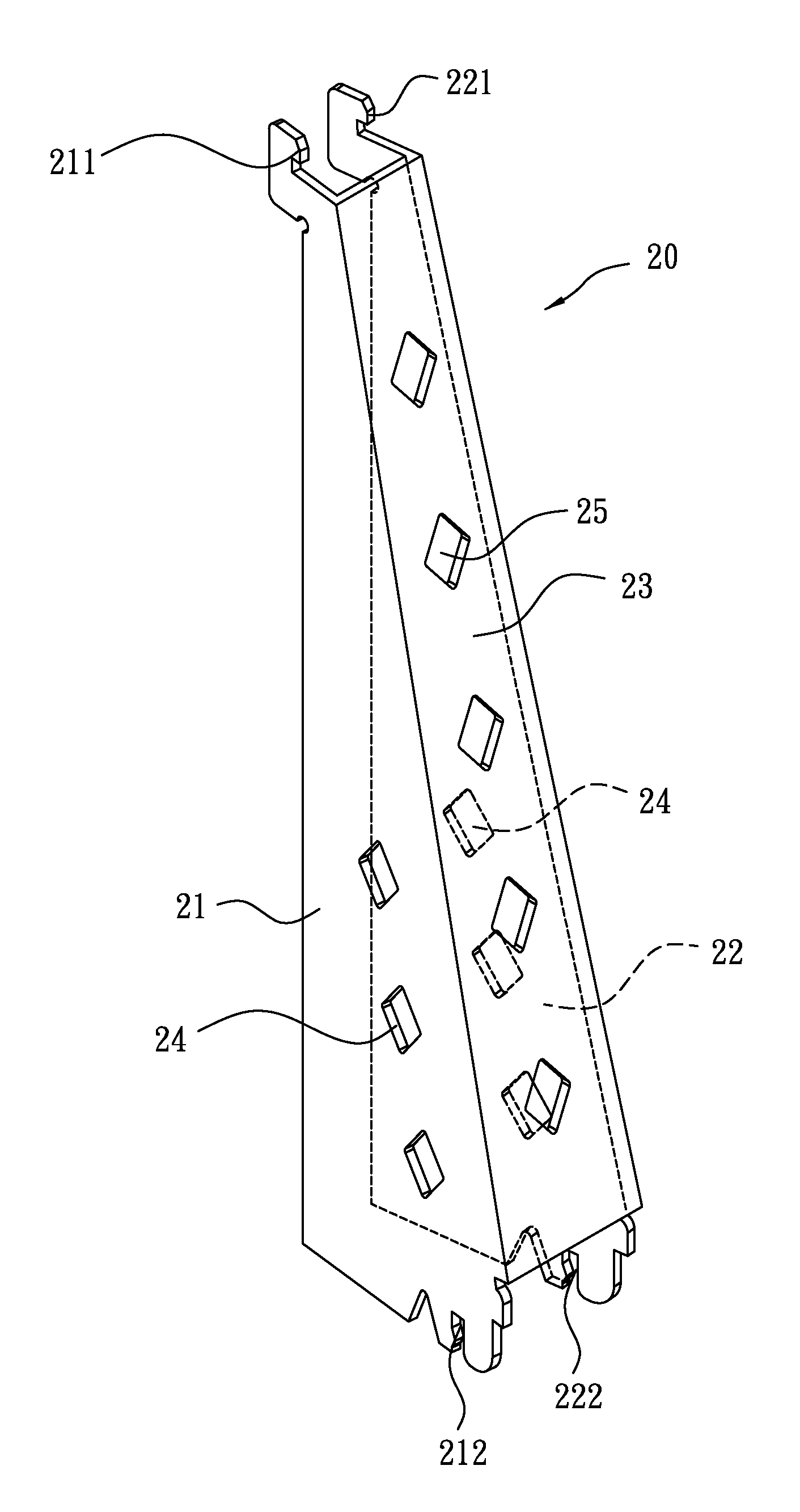
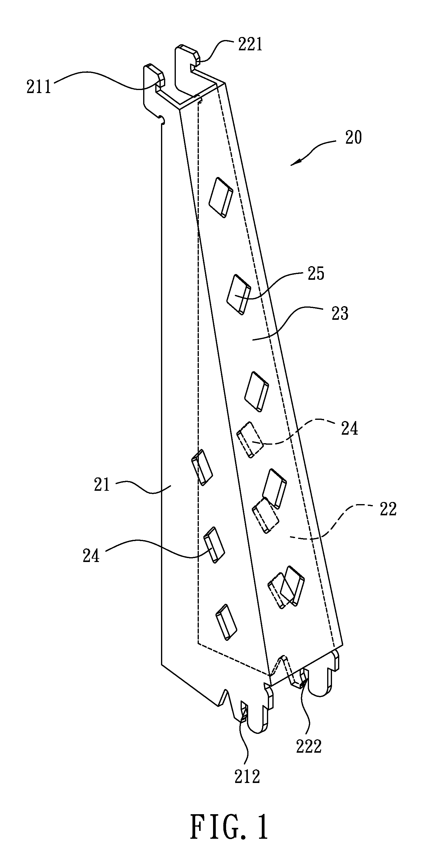
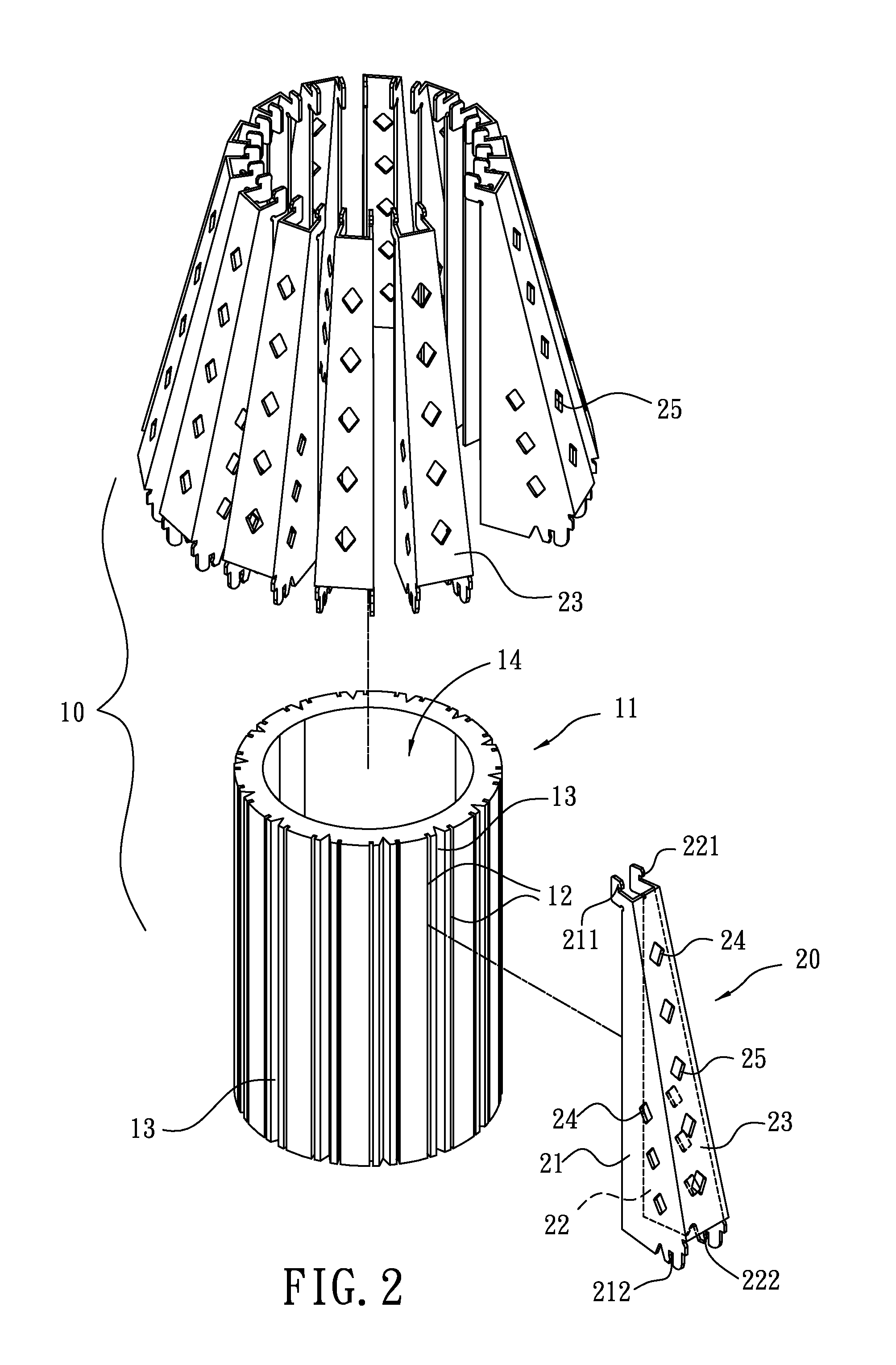
[0016]Please refer to FIGS. 1-3. The heat sink of the invention includes a tube 11 and a plurality of fins 20. The outside of the tube 11 is formed with slots 12 for being fastened by the fins 20 and grooves 13. Each of the grooves 13 is located between two adjacent ones of the slots 12 for being inserted by a mold (not shown). A hollow 14 of the tube 11 is used for receiving a heat source. Each of the fins 20 has two walls 21, 22 and a bridge 23 therebetween. The bridge can be planar or non-planar such as an arcked surface or a bent surface. Internal sides of the walls 21, 22 are separately inserted into the slots 12 so that the fins 20 are radially arranged around the tube 11. When the grooves 13 are pressed by the mold, the grooves 13 will be deformed to make the slots 12 tightly nip the fins 20.
[0017]Each of the walls 21, 22 of the fins 20 is disposed with three through holes 24 and the bridge 23 is disposed with five through holes 25. An airflow passage 26 is formed by the wall...
PUM
 Abstract
Description
Claims
Application Information
 - R&D Engineer
- R&D Manager
- IP Professional
- Industry Leading Data Capabilities
- Powerful AI technology
- Patent DNA Extraction
Browse by: Latest US Patents, China's latest patents, Technical Efficacy Thesaurus, Application Domain, Technology Topic.
© 2024 PatSnap. All rights reserved.Legal|Privacy policy|Modern Slavery Act Transparency Statement|Sitemap