Lock for sterilization container

a technology for locking containers and sterilization containers, which is applied in the field of lock for locking sterilization containers, can solve the problems of high internal pressure, inability to secure the container, and components that can be brought into locking connection with one another, and achieve the effect of reducing wear and simple handling

Active Publication Date: 2013-02-21
INNOVATIONS MEDICAL
View PDF11 Cites 29 Cited by
  • Summary
  • Abstract
  • Description
  • Claims
  • Application Information

AI Technical Summary

Benefits of technology

[0014]Accordingly, a basic object of the present invention is to design a lock for a sterilization container with a container cover and with a box-like bottom part (container housing) such that, in particular, simple handling is guaranteed, and the lowest possible wear shall be ensured.

Problems solved by technology

If was found in practice for such a lock that this is subject to increased wear because of the locking connection and also that the spring forces of the spring elements used weaken during a longer operating time, so that there is a risk that the container cover will be lifted off from the bottom part under higher internal pressures.
Since such sterilization containers must be tight when the container cover is attached, the elastically resilient components must be designed as extremely stable components in the locking variants, so that the components that can be brought into locking connection with one another are subject to extremely great wear.
If the locking forces that maintain the two components lockingly in connection with one another are too weak, there is a risk that the container cover is lifted off from the bottom part during the sterilization process and tightness is thus no longer guaranteed.
The pivot axis of the clamping strap according to the “above-dead-center principle” therefore lies in the fully closed state of the tensioning lever at the container wall of the bottom part as the mounting axis of the tensioning lever, so that independent opening of the tensioning lever is not possible.
The handling of such “classic” toggle lever locks is somewhat cumbersome, because the clamping strap freely movable at the tensioning lever must always be caused to mesh with the draw hook manually, especially for closing.
It can be seen that handling is extremely complicated in the case of this lock.

Method used


Image

  • Lock for sterilization container
  • Lock for sterilization container
  • Lock for sterilization container

Examples


Embodiment Construction

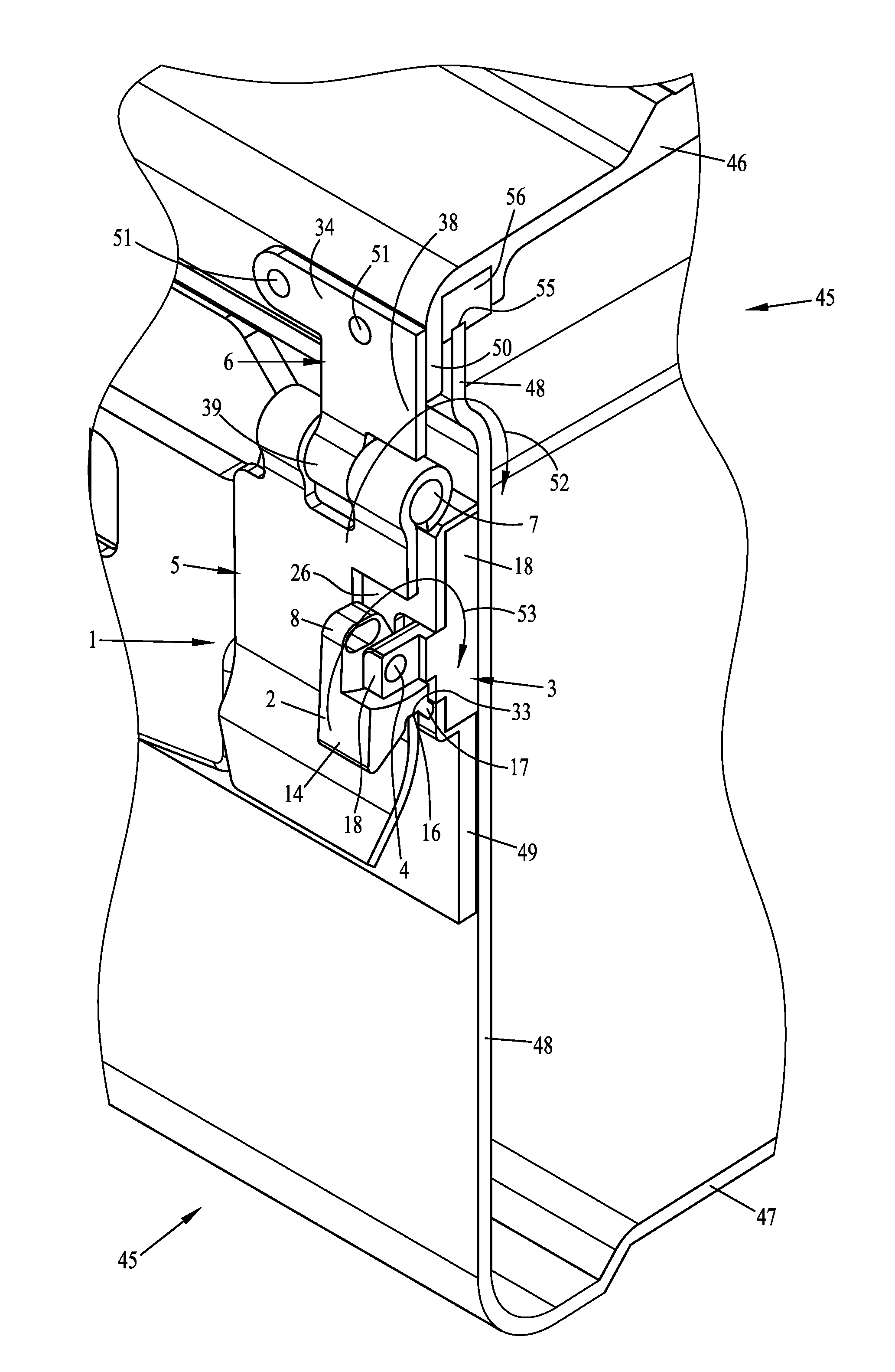
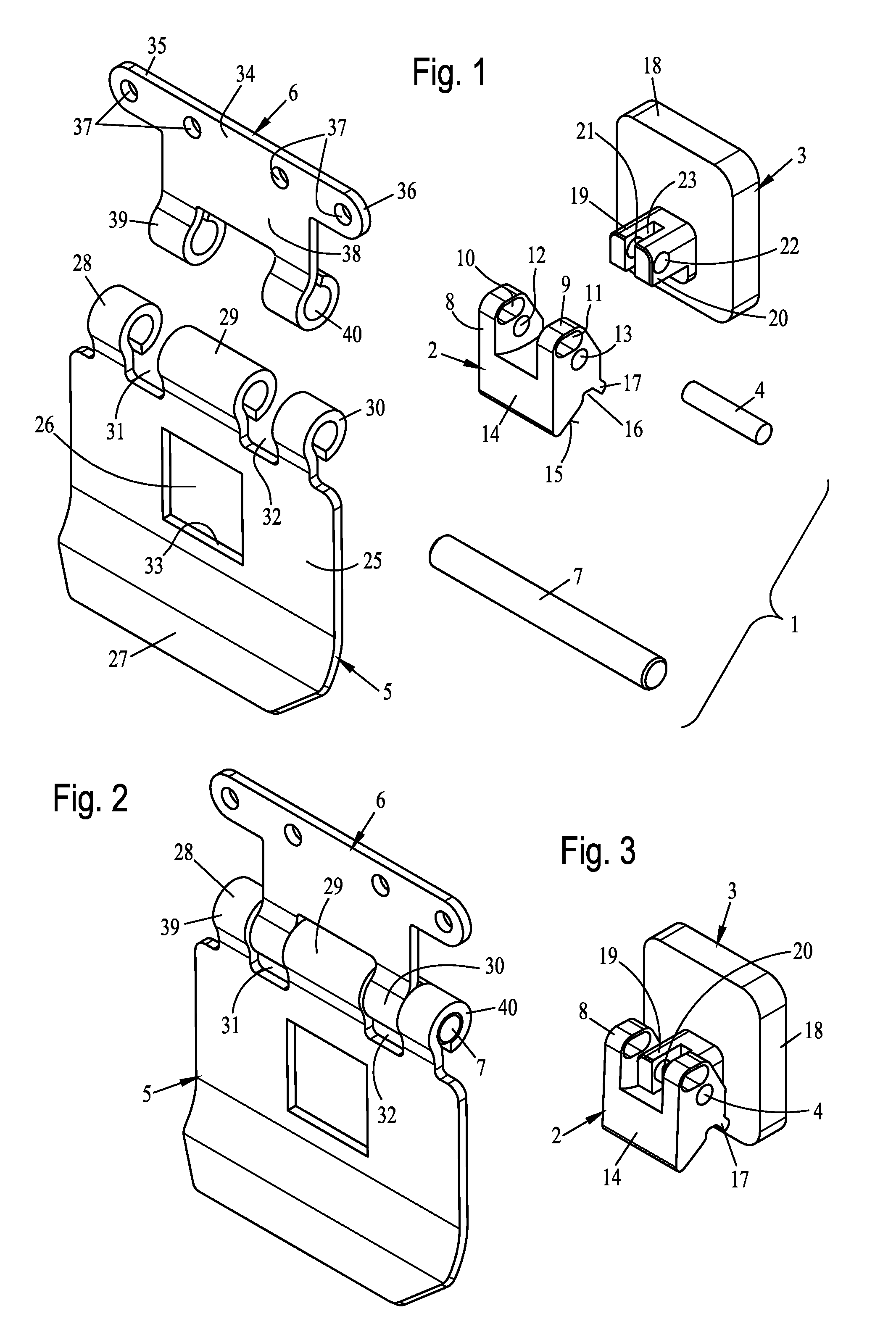
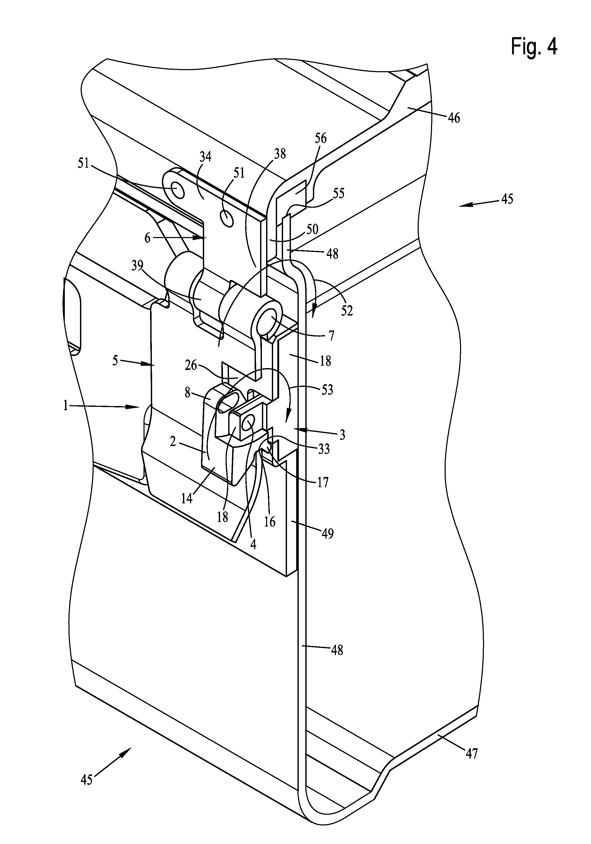
[0035]Referring to the drawings in particular, FIG. 1 shows a perspective exploded view of a possible embodiment variant of the components of a lock 1 according to the present invention. This lock 1 comprises a tensioning lever 2 and a corresponding clamping block 3, on which the tensioning lever 2 is mounted pivotably during the operation via a pivot axis 4. Furthermore, a closing flap 5 is provided, which is mounted rotatably during use at a mounting element 6 via an axis of rotation 7.

[0036]Tensioning lever 2 is of a block-like design in the embodiment variant shown and has two vertically upwardly directed mounting legs 8 and 9. In its upper end area, each of the mounting legs 8, 9 is provided with a respective elongated hole 10 and 11, which are used to secure the position of the tensioning lever 2 in the closed tensioned position thereof during the operation. Mounting holes 12 and 13, via which the tensioning lever can be received pivotably at the mounting block 3, are provided...


PUM


Abstract

A lock for locking a sterilization container has box-like bottom part and a container cover that can be removed and placed airtightly and connected on the bottom part by a seal to form a closed sterilization space. The lock has a tensioning lever pivotable into an opened position, and a closing flap rotatable about an axis of rotation, with a positive-locking closed position with the tensioning lever. The tensioning lever is able to be brought via the closing flap, during the rotary motion of the closing flap into an opened rotated position, with the closing flap disengaged from the tensioning lever after a further rotary motion into a fully opened end position. The tensioning lever may be fixed in open, and the closing flap positive-lockingly engages with the tensioning lever during closing and the tensioning lever is able be to moved into a closed tensioned position by the closing flap.

Description

CROSS REFERENCE TO RELATED APPLICATIONS[0001]This application claims the benefit of priority under 35 U.S.C. §119 of German Utility Model Application 20 2011 104 615.3 filed Aug. 17, 2011, the entire contents of which are incorporated herein by reference.FIELD OF THE INVENTION[0002]The present invention pertains to a lock for locking a sterilization container comprising a container cover and a box-like bottom part, wherein the container cover and bottom part can be removed and placed airtightly on the bottom part and connected to same by means of a sealing means arranged peripherally between the container cover and bottom part to form a closed sterilization space, wherein the lock has a tensioning lever, which can be brought from a closed position located above dead center into an opened pivoted position pivotably about a pivot axis, and that a closing flap rotatable about an axis of rotation, which is in pulling connection with the tensioning lever in a positive-locking manner in i...

Claims


Application Information

Patent Timeline
Patent Type & Authority Applications(United States)
IPC IPC(8): B65D45/16E05C19/08
CPCA61B19/026A61B2019/0229A61L2/26E05C19/14E05B63/24E05B65/52B65D45/24A61L2202/182A61B50/30A61B2050/0074Y10T292/087Y10T292/327
Inventor KREIDLER, WINFRIEDKREIDLER, JOCHEN
Owner INNOVATIONS MEDICAL
Why Eureka
Try Eureka