Printing apparatus and method for conveying sheet

a printing apparatus and sheet technology, applied in the direction of printing, thin material handling, article delivery, etc., can solve the problems of increasing the manufacturing cost of the printing apparatus, the discharged paper may not be properly aligned with the stacker, and the volume of noise from the printing apparatus tends to increase with the speed at which the sheet is conveyed, so as to achieve the effect of reducing noise and simple configuration

Inactive Publication Date: 2013-02-21
CANON KK
View PDF11 Cites 7 Cited by
  • Summary
  • Abstract
  • Description
  • Claims
  • Application Information

AI Technical Summary

Benefits of technology

[0010]Thus, in view of the above-described circumstances, an object of the present invention is to provide a printing apparatus and a method for conveying a sheet wherein generation of noise is minimized using a simple configuration, wherein, during sheet discharging, a sheet is discharged at a speed suitable for the sheet discharging, and wherein, the sheet is aligned with a sheet discharging position.

Problems solved by technology

In a series of operations from feeding of a sheet through printing by a printer or the like to sheet discharging, the volume of noise from the printing apparatus tends to increase consistently with the speed at which the sheet is conveyed.
Thus, even when the sheet discharging roller pushes the sheet out, the frictional force between the discharged sheet and the stacker or the sheets stacked in the stacker prevents the discharged sheet from reaching a regular position where the sheet is to be stacked.
Consequently, the discharged paper may fail to be properly aligned with the stacker.
Hence, if the different driving sources are used for the sheet discharging roller and the conveying roller as in the printing apparatus disclosed in Japanese Patent Laid-Open No. 2008-273636, the manufacturing cost of the printing apparatus increases.
Therefore, the state of noise at the high conveying speed may be continued for a long time.

Method used


Image

  • Printing apparatus and method for conveying sheet
  • Printing apparatus and method for conveying sheet
  • Printing apparatus and method for conveying sheet

Examples


Embodiment Construction

[0023]An embodiment of the present invention will be specifically described below with reference to the drawings. The same reference numerals denote the same or corresponding components throughout the drawings.

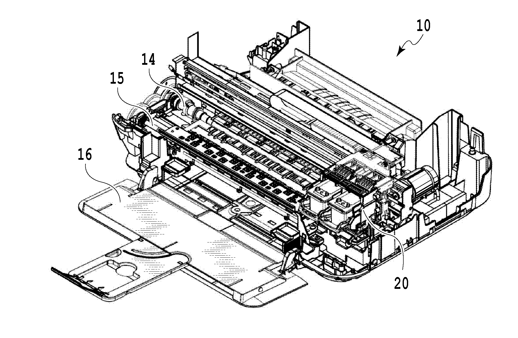
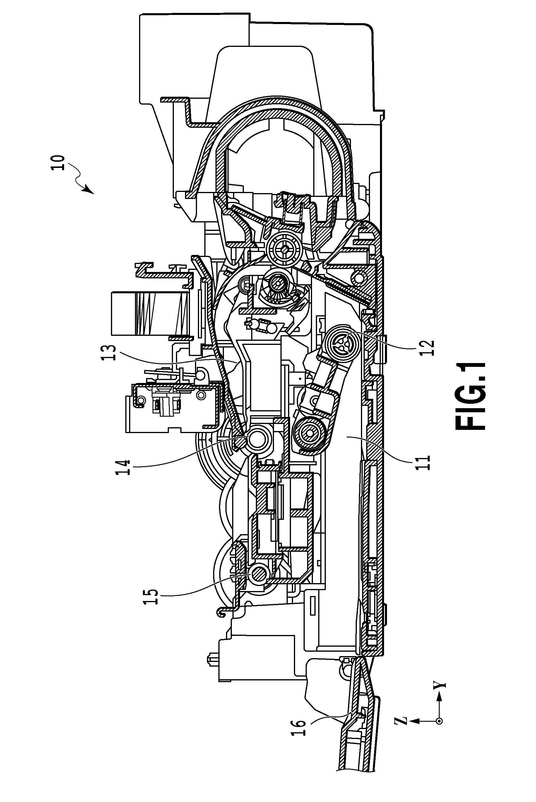
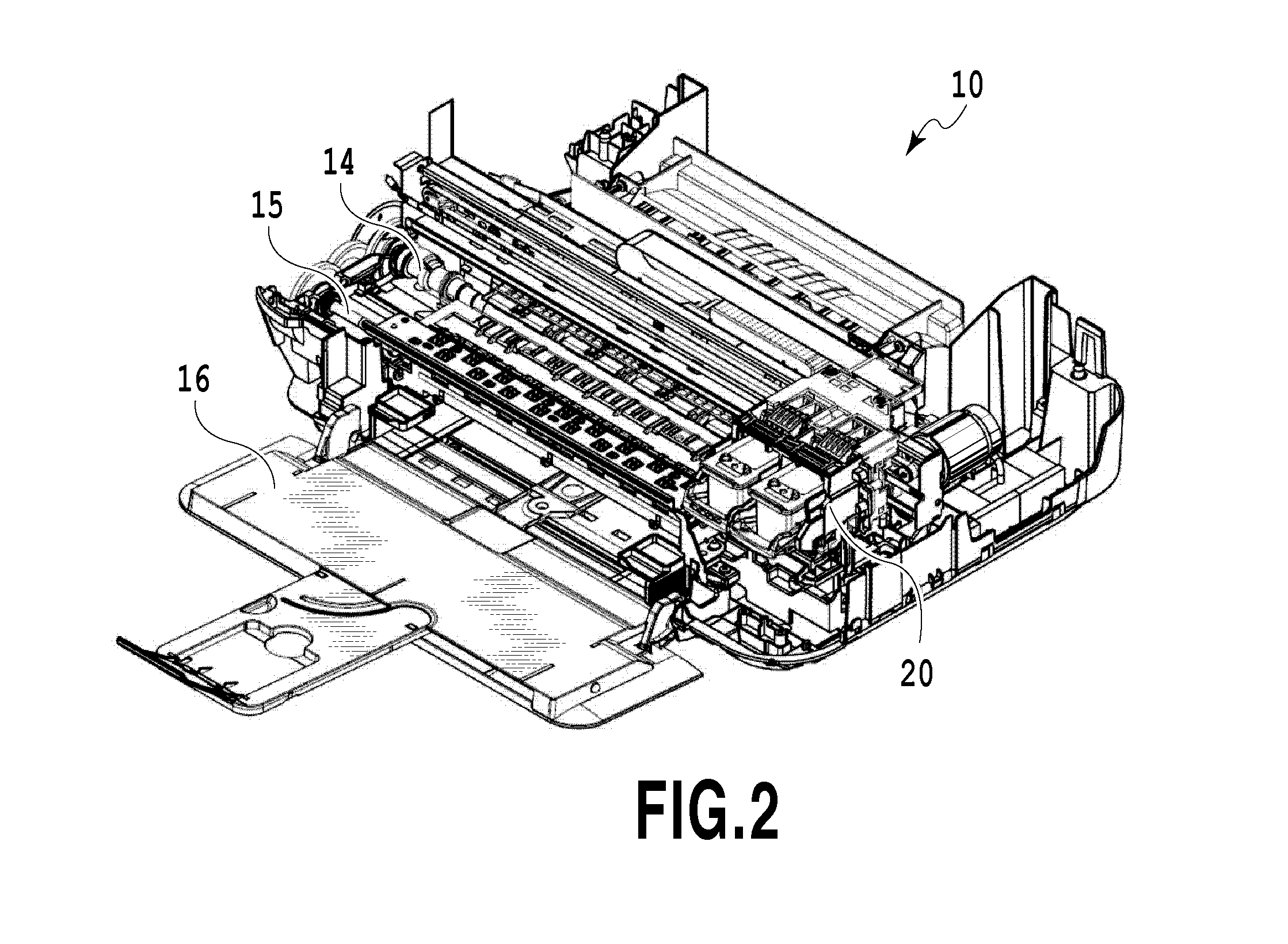
[0024]FIG. 1 is a cross-sectional view schematically showing a printing apparatus according to the present invention. FIG. 2 is a perspective view schematically showing the printing apparatus. In FIG. 1, a printing apparatus 10 includes a sheet feeding roller 12 for feeding sheets (not shown in the drawing), a conveying roller 14, and a sheet discharging roller 15. The sheet feeding roller (sheet feeding unit) 12 is located in a conveying path L upstream of the conveying roller 14 to feed sheets to the conveying path L. The sheet feeding roller 12 feeds sheets to the conveying path L by rotating in condition that the sheet feeding roller 12 contacts to the sheet. In this case, the sheet feeding roller 12 feeds sheets by rotation of one roller. In the present embodiment, sheets...


PUM


Abstract

The present invention provide a printing apparatus and a method for conveying a sheet wherein generation of noise is minimized using a simple configuration, wherein, during sheet discharging, a sheet is discharged at a speed suitable for the sheet discharging, and wherein the sheet is aligned at a sheet discharging position. The printing apparatus controls conveyance of sheets as follows. A first sheet and a second sheet fed subsequently to the first sheet are conveyed at a relatively low conveying speed until an upstream trailing end of the first sheet is placed at a sheet discharging standby position. Then, the first sheet is discharged to the sheet discharging position, and the first sheet and the second sheet are conveyed at a relatively low conveying speed until a downstream leading end of the second sheet is placed at a sheet feeding control position.

Description

BACKGROUND OF THE INVENTION[0001]1. Field of the Invention[0002]The present invention relates to a printing apparatus and a method for conveying a sheet wherein a printed sheet is discharged after being aligned with a predetermined sheet discharging position.[0003]2. Description of the Related Art[0004]Printing apparatuses such as printers include a sheet discharging mechanism for discharging a sheet completely printed by a printing section after aligning the sheet with a predetermined sheet discharging position outside the apparatus. The sheet discharging mechanism in such a printing apparatus is configured such that a sheet discharging roller that is rotated by a driving source is compressed against a sheet and then rotated to exert a conveying force on the sheet, which is thus discharged to the exterior of the apparatus and stacked in a stacker.[0005]In a series of operations from feeding of a sheet through printing by a printer or the like to sheet discharging, the volume of noi...

Claims


Application Information

Patent Timeline
Patent Type & Authority Applications(United States)
IPC IPC(8): B65H29/20B65H5/06
CPCB41J13/0009B65H2511/22B65H7/20B65H2511/20B65H2513/10B65H2513/51B65H2601/521B65H2801/06B65H29/14B65H29/125B65H2511/414B65H2511/514B65H2220/01B65H2220/02B65H2220/03B65H2701/1313
Inventor TAKAYAMA, YUJI
Owner CANON KK
Why Eureka
Try Eureka