
Fluid pump

a technology of fluid pump and inlet plate, which is applied in the direction of fluid engine, transverse flow pump, non-positive displacement pump, etc., can solve the problems of objectionable high frequency noise, and achieve the effect of minimizing the fluid hammer effect, minimizing and minimizing the noise generated by the vibration of the inlet pla

Inactive Publication Date: 2017-01-26
DELPHI TECH IP LTD
View PDF21 Cites 1 Cited by
  • Summary
  • Abstract
  • Description
  • Claims
  • Application Information

AI Technical Summary

Benefits of technology

The fluid pump has a structure that reduces noise and vibration during operation, minimizing the fluid hammer effect. This is achieved through the arrangement of an inlet plate flow channel with a first region at least 150 degrees in angle and a second region from 61.8 to 71.8 degrees in angle. The invention also involves a pumping member rotated by a motor, which helps to smoothly pump fluid from the inlet to the outlet.

Problems solved by technology

Motion of the blades of the impeller causes fluid pressure fluctuations which in turn causes vibration of the inlet plate which propagates through the rest of the structure of the fuel pump.
Furthermore, when the fuel reaches the end of the inlet channel, a fluid hammer effect may be produced, thereby resulting in a high frequency noise that may be objectionable.

Method used


Image

  • Fluid pump
  • Fluid pump
  • Fluid pump

Examples


Embodiment Construction

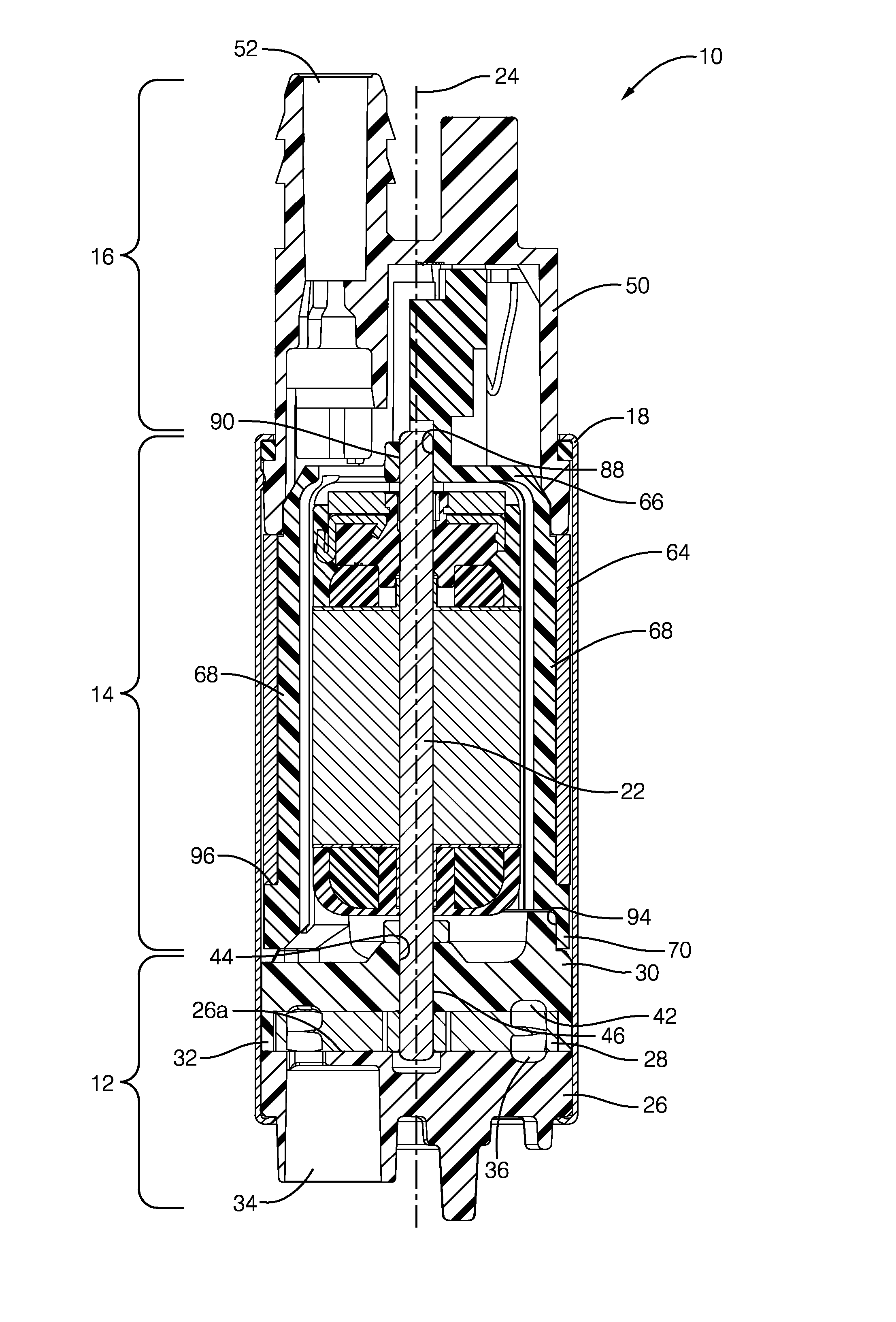
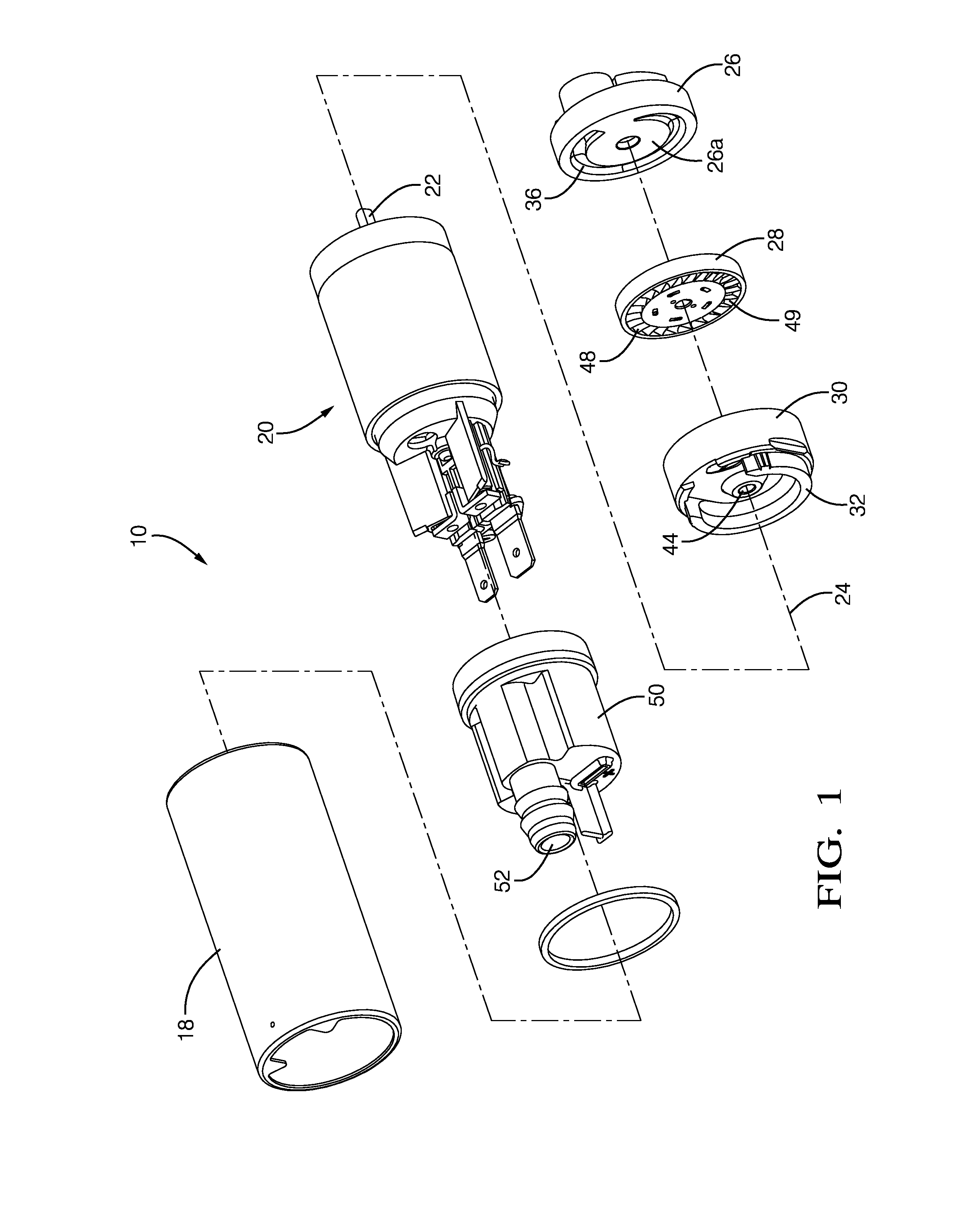
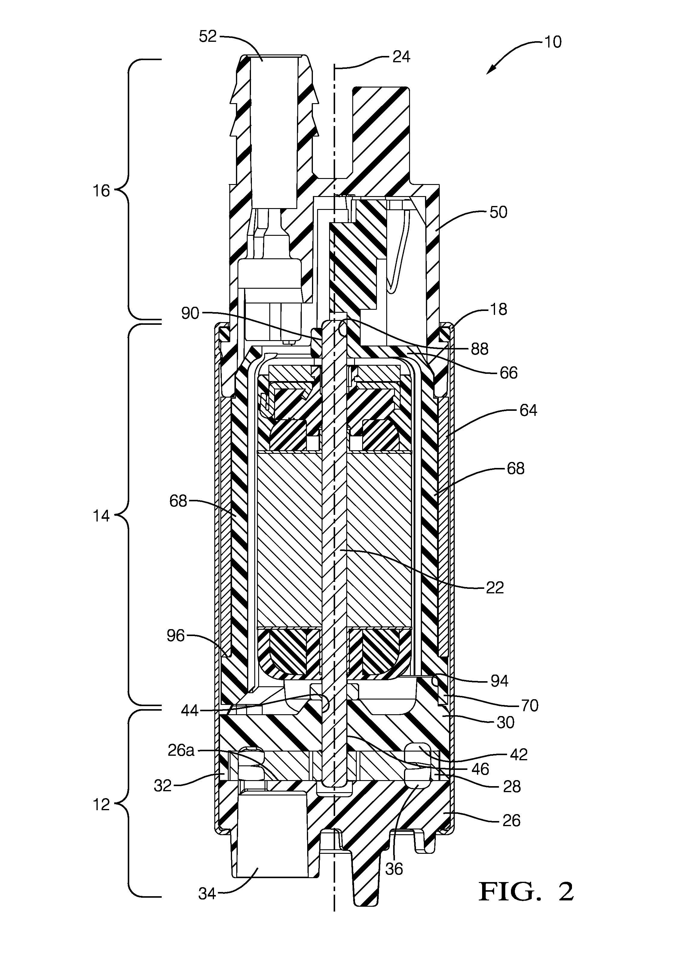
[0015]Reference will be made to FIGS. 1 and 2 which are an exploded isometric view and an axial cross-sectional view respectively of a fluid pump illustrated as fuel pump 10 for pumping liquid fuel, for example gasoline or diesel fuel, from a fuel tank (not shown) to an internal combustion engine (not shown). While the fluid pump is illustrated as fuel pump 10, it should be understood that the invention is not to be limited to a fuel pump, but could also be applied to fluid pumps for pumping fluids other than fuel. Fuel pump 10 generally includes a pump section 12 at one end, a motor section 14 adjacent to pump section 12, and an outlet section 16 adjacent to motor section 14 at the end of fuel pump 10 opposite pump section 12. A housing 18 of fuel pump 10 retains pump section 12, motor section 14 and outlet section 16 together. Fuel enters fuel pump 10 at pump section 12, a portion of which is rotated by motor section 14 as will be described in more detail later, and is pumped past...


PUM


Abstract

A fluid pump includes an inlet; an outlet; a motor; and an impeller rotated by the motor about an axis, the impeller being positioned axially between an inlet plate and an outlet plate. The inlet plate includes a channel that receives fluid from the inlet, the channel being defined by an inner wall and an outer wall. The channel has a first region extending over an angle of at least 150° and a second region extending from the first region over an angle of 61.8° to 71.8°. The inner wall has a first radius centered about the axis which is constant over the first region and the second region. The outer wall has a second radius centered about the axis which is constant over the first region and also has a third radius not centered about the axis which is constant over the second region.

Description

TECHNICAL FIELD OF INVENTION[0001]The present invention relates to a fluid pump; more particularly to a fuel pump; even more particularly to a fuel pump with an electric motor which rotates an impeller that is located axially between an inlet plate and an outlet plate; and still even more particularly to an inlet plate flow channel of the inlet plate which minimizes noise due to structural vibrations induced by fluid hammer at the end of the inlet plate flow channel.BACKGROUND OF INVENTION[0002]Fluid pumps, and more particularly fuel pumps for pumping fuel, for example, from a fuel tank of a motor vehicle to an internal combustion engine of the motor vehicle, are known. U.S. Pat. No. 6,824,361 to Yu et al. shows a typical electric fuel pump which includes and impeller with a plurality of blades that is located axially between stationary inlet and outlet plates. The inlet plate includes an inlet which allows fuel to enter the fuel pump such that the inlet is in fluid communication wi...

Claims


Application Information

Patent Timeline
Patent Type & Authority Applications(United States)
IPC IPC(8): F04D29/66F04D29/52F04D13/06
CPCF04D29/669F04D29/528F04D13/0686F02M37/0011F02M37/0041F02M37/08F04D5/002F04D5/007F04D13/0693
Inventor HERRERA, DANIELJESWANI, PARTABFISCHER, JOHN G.ASLAM, MOHAMMED
Owner DELPHI TECH IP LTD
Learn More