Mixer assembly for digestion tank

a technology of mixing assembly and digestion tank, which is applied in the direction of biological water/sewage treatment, sustainable biological treatment, biological sludge treatment, etc., can solve the problems of wriggling/deflection of the mixing assembly, the risk of damage to the mixing chamber, and the steel ring or its attachment to the chamber

Inactive Publication Date: 2013-02-21
XYLEM IP HLDG
View PDF7 Cites 11 Cited by
  • Summary
  • Abstract
  • Description
  • Claims
  • Application Information

AI Technical Summary

Benefits of technology

[0007]The present invention aims at obviating the above-mentioned disadvantages and failings of previously know mixer assemblies and at providing an improved mixer assembly. A primary object of the present invention is to provide an improved mixer assembly of the initially defined type, which secure that neither the mixer assembly nor the chamber runs the risk of getting damaged if unbalance / wriggling arises in the output shaft.

Problems solved by technology

If an unbalance appear in the mixer assembly, i.e. if the output shaft starts to perform a nutatinq movement or starts to deflect / oscillate during rotation or wriggle, and the mixer assembly is not immediately turned off, the mixer assembly as well as the chamber runs the risk of getting damaged.
Unbalance may for instance arise due to the fact that a blade has come loose from the propeller unit, that solid material has become stock to the blades of the propeller unit, that a settlement / inclination of the tank takes place which makes the drive unit to incline in relation to a plumb line, etc.
If unbalance arises and the output shaft starts to wriggle, its wriggling / deflection will be limited by the steel ring.
However, the steel ring or its attachment to the chamber will already after a, in this connection, short time be damaged if the mixer assembly is not turned off.
This known solution also requires an unnecessarily long and expensive output shaft.
However, this constructional limitation may lead to the fact that the optimal length of the specific application cannot be used due to the inherent natural frequency of the output shaft.

Method used


Image

  • Mixer assembly for digestion tank
  • Mixer assembly for digestion tank
  • Mixer assembly for digestion tank

Examples


third embodiment

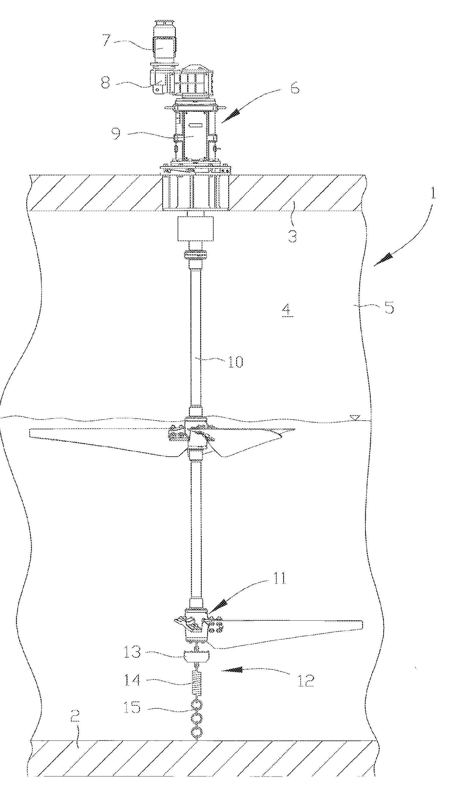
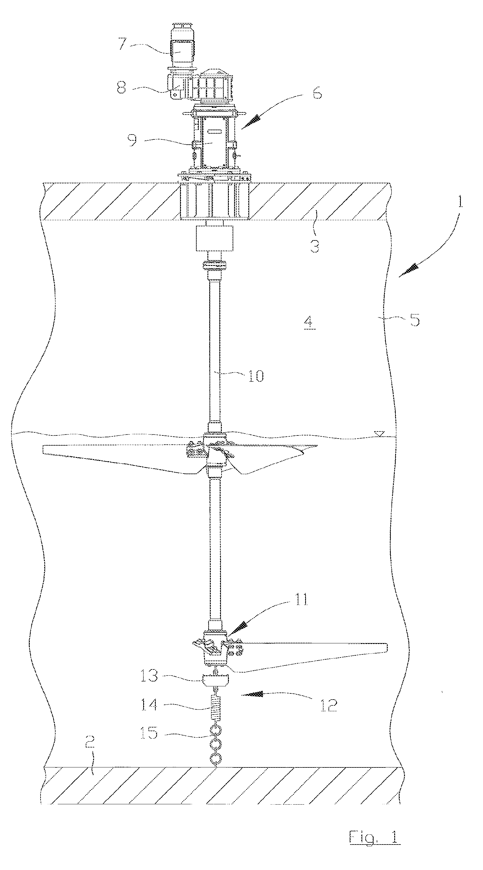
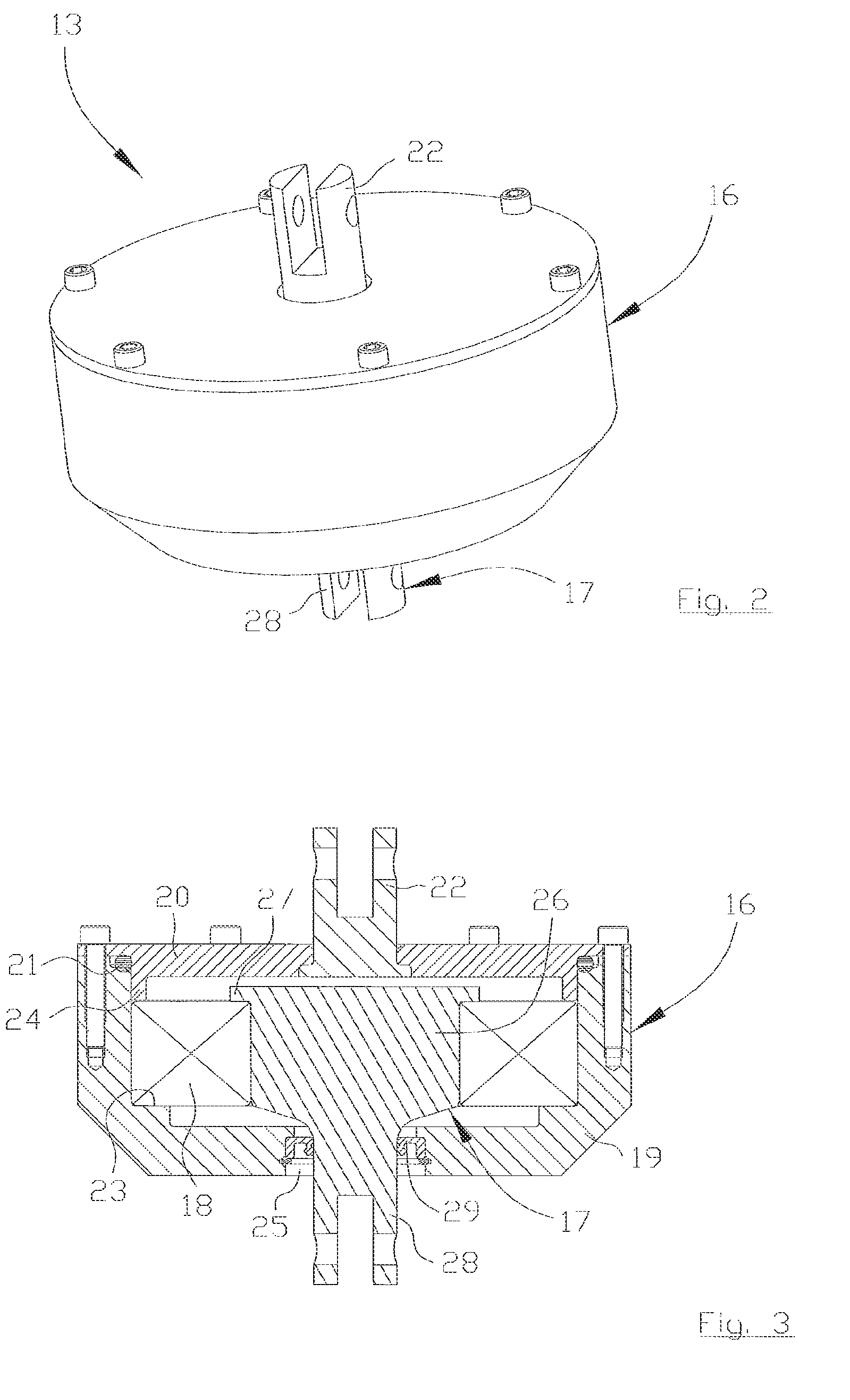
[0029]Reference is now also made to FIGS. 2-6, in which a first, a second and a third embodiment, respectively, of the swivel 13 are shown. The swivel 13 comprises in the shown embodiments a first element 16 arranged to be driven in rotation about the output shaft 10 of the mixer assembly 6, a second element 17 arranged to be connected to said floor 2 of the chamber 1, and a bearding 18 arranged at the interface between the first element 16 and the second element 17. The bearing 18 is arranged to admit mutual rotation between the first element 16 and the second element 17, and to transmit an axially directed pulling force between the first element 16 and the second element 17.

first embodiment

[0030]According to the swivel 13, see FIGS. 2 and 3, the first element 16 comprises a bowl shaped house 19 and a lid 20 cooperating with the house 19. The lid 20 is preferably releasably connected to the house 19. Furthermore, a sealing 21 is arranged at the interface between the lid 20 and the house 19, in order to prevent the material present in the chamber 1 from entering and running the risk, of damaging the swivel 13. Further, a first connection. 22 of the swivel 13 is fixedly connected to the lid 20, which first connection 22, in the preferred embodiment of the stabilizer 12, is arranged to be connected to an interacting connection not shown) of the output shaft 10 of the mixer assembly 6.

[0031]On the inside of the house 19 is presented a bearing seat. 23 for the bearing 18, which in the axial direction preferably is fixed to the bearing seat 23 by a collar 24 of the lid 20 interjecting into the house 19. Alternatively a clamp ring (not shown) or the like may be used to fixate...

second embodiment

[0039]The first connection 22 is, in the preferred embodiment of the stabilizer 12, arranged to be connected to the cooperating connection of the output shaft 10 of the mixer assembly 6. It shall be pointed out that the swivel 13 may be turned 180 degrees about a horizontal axis such that the second element 17 is arranged to be connected to cooperating connection of the output shaft 10 of the mixer assembly 6, and that the first element 16 is arranged to be connected to the resilient element 14.

[0040]Reference is now made to FIG. 6, in which elements corresponding to elements in the first embodiment according to FIGS. 2 and 3 are denoted by the same reference number. According to the third embodiment of the swivel 13 the first element 16 comprises a bowl shaped house 19 and preferably a lid 20 cooperating with the house 19. The lid 20 is preferably releasably connected to the house 19. Furthermore, a sealing 21 is arranged at the interface between the house 19 and the lid 20, in or...


PUM

PropertyMeasurementUnit
depthaaaaaaaaaa
depthaaaaaaaaaa
distanceaaaaaaaaaa

Abstract

The invention relates to a mixer assembly for agitating material in a digestion tank (1), comprising a drive unit (7, 8, 9) and an output shaft (10) extending from said drive unit, which output shaft is arranged to hang down into said digestion tank (1) rotatably suspended from the drive unit. According to the invention the mixer assembly (6) furthermore comprises a stabilizer (12) comprising a swivel (13) and at least one resilient element (14) connected to said swivel (13), the stabilizer (12) being connected to the lower end of the output shaft (10) of the mixer assembly (6) and being arranged to be connected to a floor (2) of said digestion tank.

Description

TECHNICAL FIELD OF THE INVENTION[0001]The present invention relates in general to a digestion tank for digestion of excrements, but also other applications comprising a chamber and a mixer assembly are referred to. The material present in the chamber is referred to as a fluid mixture, a suspension, a solid material in the form of powder or granulate, etc., requiring agitation. The present invention relates especially to a mixer assembly for agitating material in a chamber, which mixer assembly comprises a drive unit and an output shaft extending from said drive unit, which output shaft is arranged to hang down into said chamber rotatably suspended from the drive unit.BACKGROUND OF THE INVENTION AND PRIOR ART[0002]A common type of digestion tank comprises a mixer assembly for agitating the excrement, or mixture of fluid and sludge, present in the chamber. Such applications comprise tanks having a depth from about 10 meters to about 40 meters, however a common depth is about 15-25 met...

Claims


Application Information

Patent Timeline
Patent Type & Authority Applications(United States)
IPC IPC(8): B01F7/16B01F27/80B01F27/91B01F35/00B01F35/41
CPCA01C3/026B01F7/22B01F15/00707F16C2320/16C02F11/04C02F2103/005C02F2203/006C02F3/2866B01F27/91B01F35/4121B01F27/80B01F35/00C12M21/04C12M27/02F16F15/00Y02W10/10
Inventor SELENIUS, PER
Owner XYLEM IP HLDG
Why Eureka
Try Eureka