Underwater Camera Housing

a technology for underwater cameras and housings, applied in the field of underwater video camera housings, can solve the problems of limiting the user's ability to orient underwater cameras, affecting the lens of underwater cameras, and complicated current configurations

Inactive Publication Date: 2013-02-21
WESSNER DAVID HOWARD
View PDF8 Cites 1 Cited by
  • Summary
  • Abstract
  • Description
  • Claims
  • Application Information

AI Technical Summary

Problems solved by technology

However, the current configurations are complicated and will limit a user's ability to orient the underwater camera as a result of the bulk and amount of connecting wires and equipment, as well as fishing lines, lures, or bait to traverse along with one's watercraft while simultaneously recording desired views.
The power supply and video cable, while interfering with control over the orientation of the device, will also frequently interfere with the lens of the camera, partially or completely bloc

Method used


Image

  • Underwater Camera Housing
  • Underwater Camera Housing
  • Underwater Camera Housing

Examples


Embodiment Construction

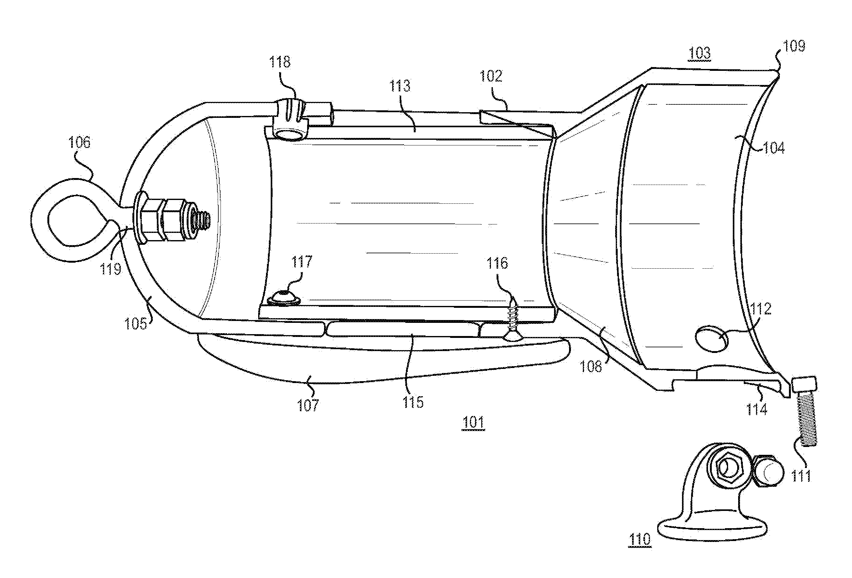
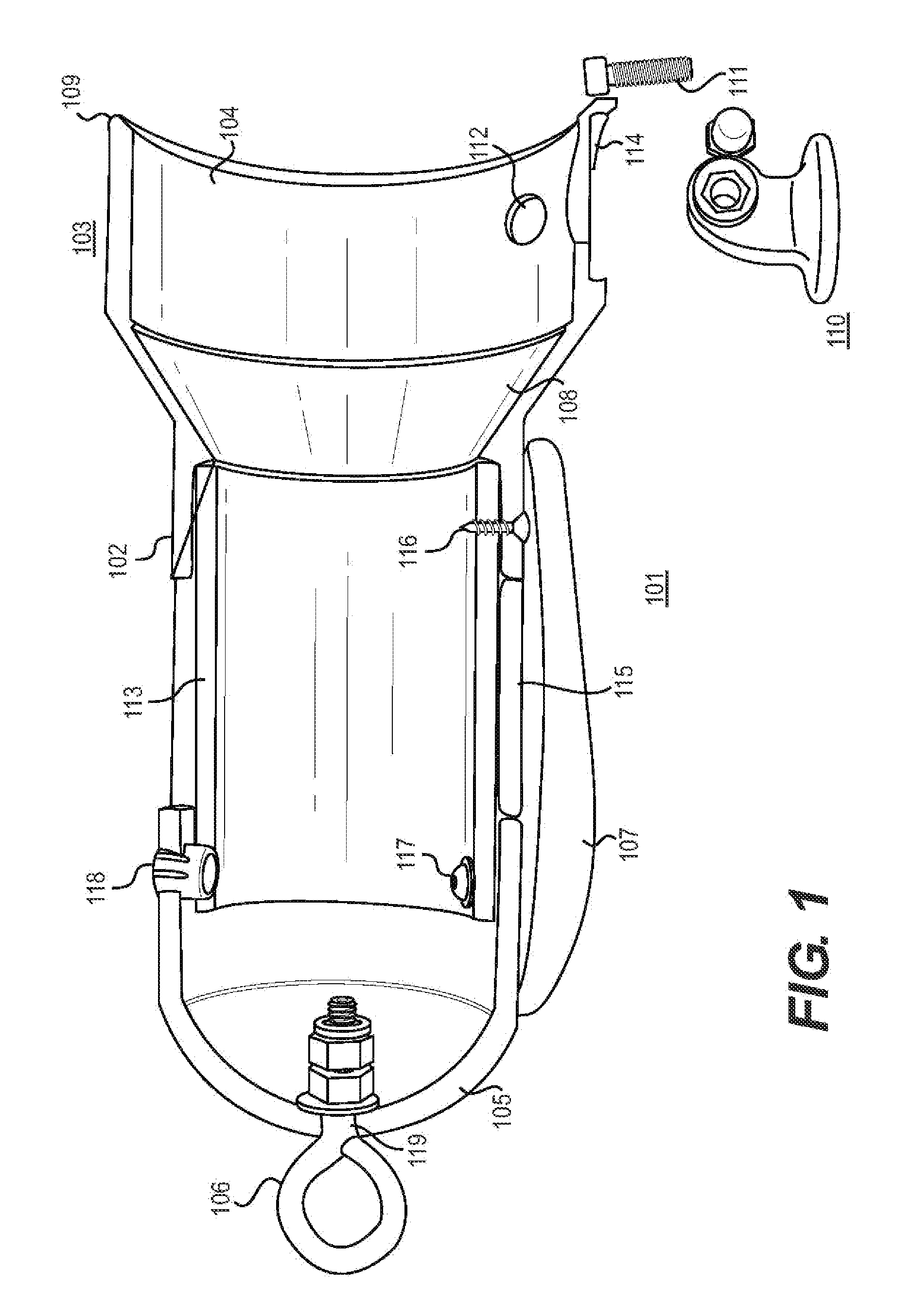
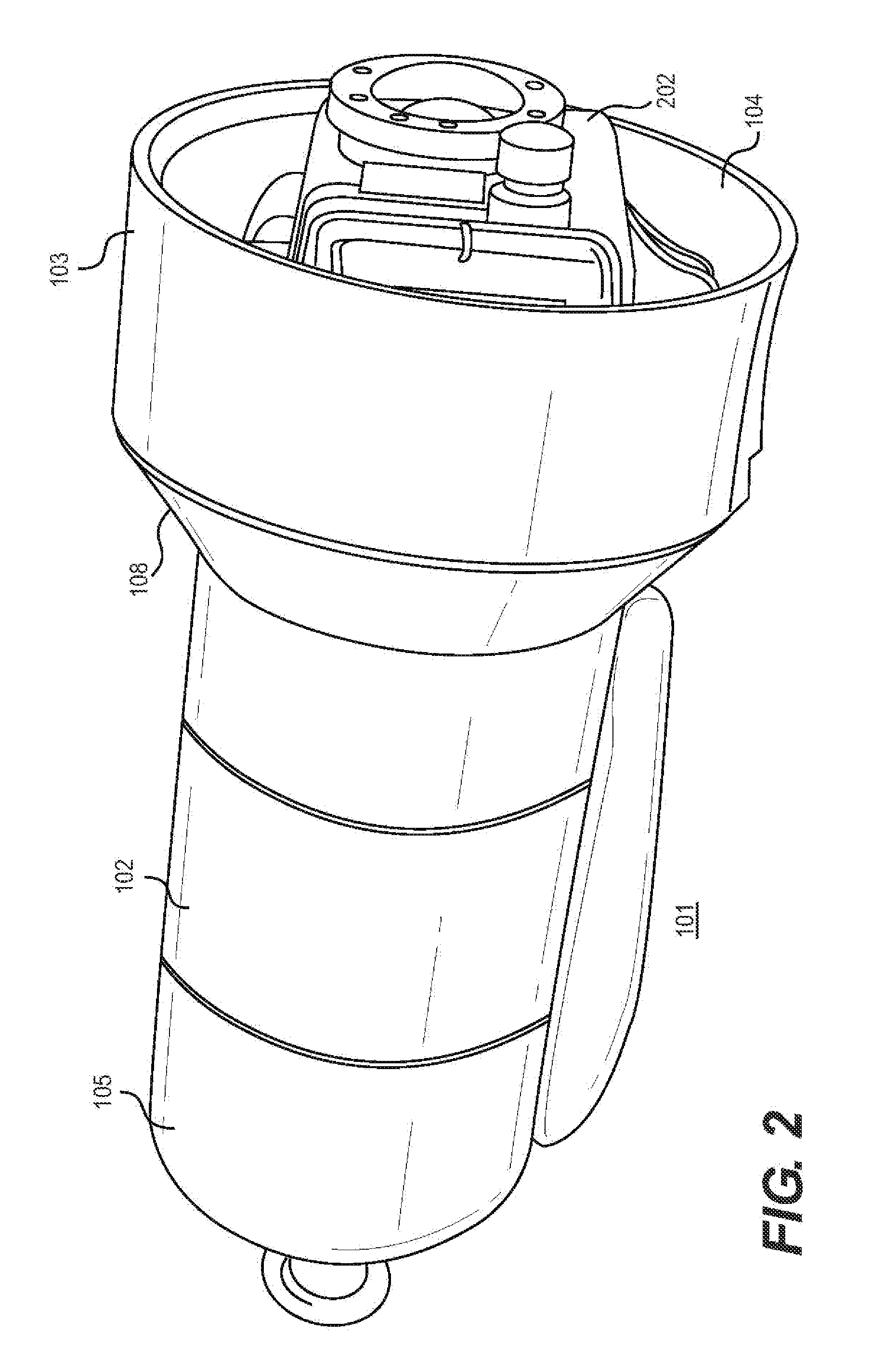
[0024]Referring now to FIG. 1, an exterior view of an embodiment of the present invention is shown. The housing 101 comprises a tubular portion 102, a rear portion 103 that has a larger circumference than the tubular portion 102, with an opening 104 in the rear portion 103. The front portion 105, which is distal to the rear portion 103, is closed and preferentially rounded. The front portion 105 further comprises attachment means 106. The attachment means 106 is utilized to attach a towing or hanging line (not shown). The attachment means 106 is shown as a loop of metal, but it will be understood that the attachment means may be constructed of any material and any shape utilized in the art to attach towing and hanging lines to submersible equipment. It will be further understood that the invention is intended to be useful for towing by a watercraft; as such, attachment means 106 that are well known in the art for towing equipment and devices from watercraft, and may include fixed or...


PUM


Abstract

A camera housing for underwater use comprising a turbulence-reducing design, a recess for mounting a camera, attachment means, and stabilizing outer shell and keel design.

Description

[0001]This invention claims the benefit of the filing date of U.S. Provisional Patent Application No. 61 / 443,354, filed on Feb. 16, 2011FIELD OF THE INVENTION[0002]The present invention relates generally to an apparatus for utilizing with an underwater camera device. More particularly, the present invention is an underwater video camera housing which can suspend from a watercraft and record underwater views.BACKGROUND OF THE INVENTION[0003]Conventional means of underwater recording requires using a video camera with a removable head; the cabling, boat-mounted power supply, monitoring and recording equipment all connect to the video camera through the removable head.[0004]In order to record video, the user (whether it is the boat operator, research or fishing crew, or the like) must employ a bulky power supply and video cable between the underwater camera and the support and operation equipment located on the boat. This generally includes boat-mounted ancillary recording devices, ope...

Claims


Application Information

Patent Timeline
IPC IPC(8): G03B17/08
CPCG03B17/08A01K91/06
Inventor WESSNER, DAVID H.
Owner WESSNER DAVID HOWARD
Why Eureka
Try Eureka