Method and a network node for improving bandwidth efficiency in an optical network

a technology of optical network and network node, which is applied in the direction of transmission monitoring, transmission monitoring/testing/fault-measurement systems, electrical devices, etc., can solve the problems of inability to deploy channels with bit rate higher, inability to meet the requirements of bandwidth, and inability to achieve the capacity limit of 50 ghz fixed grid, etc., to achieve the effect of improving bandwidth/spectral efficiency

Inactive Publication Date: 2013-02-21
ECE TELECOM LTD
View PDF4 Cites 42 Cited by
  • Summary
  • Abstract
  • Description
  • Claims
  • Application Information

AI Technical Summary

Benefits of technology

[0021]In other words, it can be formulated as a method for improving bandwidth / spectral efficiency in an optical network by dynamically utilizing unused spacing around preliminarily allocated optical channels, by monitoring actual bandwidth of the preliminarily allocated optical channels incoming a node of the optical network, reporting the monitoring results to a node controller of said node and further to a network controller, receiving recommendations of the network controller at said node, adjusting bandwidth of one or more of the allocated optical channels thereby freeing spare bandwidth spacing for inserting one or more additional optical channels.

Problems solved by technology

To the best of the Applicant's knowledge, prior art solutions do not resolve the problem of effective bandwidth utilization in optical networks where various grids may co-exist, or where additional optical channels need to be inserted between existing channels.
Only recently, technological limitations of the capacity has been reached with channels at 100 Gbit / s operating on both polarization planes at 50 GHz grid and providing spectral efficiency of 2 bit / s / Hz.
In other words, a fixed grid of 50 GHz does not allow deploying a channel with bit rate higher than 100 Gbps, since the bandwidth required for such a high rate signal is greater than the channel spacing so that neighbor channels start overlapping one another.

Method used


Image

  • Method and a network node for improving bandwidth efficiency in an optical network
  • Method and a network node for improving bandwidth efficiency in an optical network
  • Method and a network node for improving bandwidth efficiency in an optical network

Examples


Embodiment Construction

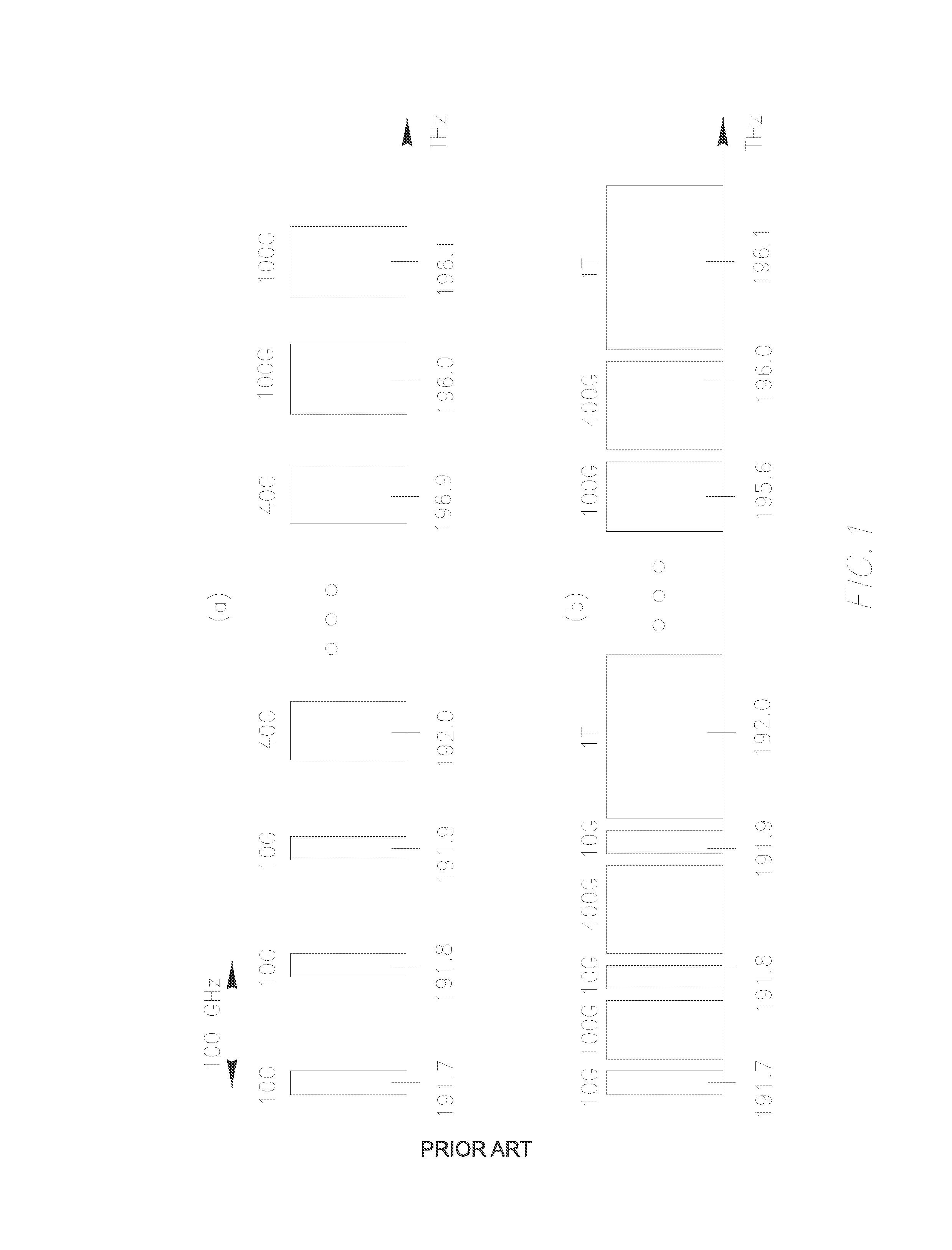
[0062]FIG. 1A illustrates a conventional 100 GHz channel spacing DWDM channel allocation with 10 Gb / s, 40 Gb / s and 100 Gb / s channels, while FIG. 1b—a bandwidth-flexible DWDM channel allocation which would be suitable for supporting future 1-Tb / s and 400-Gb / s superchannels along with 100 Gb / s channels.

[0063]FIGS. 1A and 1B show an example of comparison of the fixed ITU-T grid and a flexible grid for the C-band. When implementing a flexible grid, issues such as nonlinearity from mixed signal formats, and bit rates and optical power control when the number of channels varies dynamically must be considered. Also, operational and management issues such as channel numbering and bandwidth assignment need to be addressed. ROADMs with flexible bandwidth design are required to support dynamic add / drop of channels beyond 100 Gb / s.

[0064]The channel spacing in modern optical networks is typically 100 GHz, as shown in FIG. 1A; the figure allows seeing essential waste of unused optical bandwidth, ...


PUM


Abstract

A method and system are provided for improving bandwidth efficiency in an optical network by dynamically utilizing unused bandwidth located around preliminarily allocated optical channels. The method comprising monitoring actual bandwidth of the preliminarily allocated optical channels incoming to a node of the optical network, reporting the monitoring results to the controller of that node and further to a network controller, receiving at that node recommendations generated by the network controller, adjusting bandwidth of one or more of the allocated optical channels thereby releasing spare bandwidth for inserting one or more additional optical channels thereat.

Description

CROSS-REFERENCE TO RELATED APPLICATIONS[0001]This application claims priority of Israel Patent Application No. 214391, filed Aug. 1, 2011, the disclosure of which is incorporated by reference herein in its entirety.TECHNICAL FIELD[0002]The present invention relates to technologies for dynamic management of bandwidth in optical networks to improve bandwidth efficiency, and in particular—for improving management of the optical bandwidth in network sections comprising channels of gridless or mini-grid flexible networks.BACKGROUND[0003]Flexibility to support mesh topologies, dynamic capacity allocation, and automatic network control and light path setup are key elements in the design of next-generation optical transport networks. To realize these capabilities, Reconfigurable Optical Add / Drop Multiplexers (ROADM) with dynamic add / drop structures, embedded control planes, and light-path characterization are required. A light path is a pre-established optical circuit carrying an optical ch...

Claims


Application Information

Patent Timeline
Patent Type & Authority Applications(United States)
IPC IPC(8): H04B10/08
CPCH04J14/0224H04J14/0257H04J14/0282H04J14/0204H04J14/0208H04J14/0212H04J14/0267
Inventor DAHAN, DAVID JIMMYMAHLAB, URI
Owner ECE TELECOM LTD
Why Eureka
Try Eureka