Cask handling system and method

a cask and container technology, applied in the field of systems and methods for handling massive containers, can solve the problems of insufficient documentation of existing systems, use of out-of-date technology, and large man-hours required

Active Publication Date: 2013-02-21
MHE TECH
View PDF23 Cites 17 Cited by
  • Summary
  • Abstract
  • Description
  • Claims
  • Application Information

AI Technical Summary

Benefits of technology

[0005]Also disclosed is a method for removing spent nuclear fuel comprising the steps of moving a cask below an opening at a first station using a self-powered transporter, rotating the cask from a horizontal orientation to a vertical orientation at the first station, moving the cask below hoist at a second station using the self-powered transporter, moving the cask below a penetration at a second station using the self-powered transporter, raising the cask from the self-powered transporter to the penetration, securing the cask to the penetration, inserting the spent fuel into the cask, unsecuring the cask from the penetration, and lowering the cask onto the self-powered transporter.
[0006]Further disclosed is a self-powered vehicle for transporting a spent nuclear fuel cask having pairs of upper and lower trunnions. The vehicle comprises, in combination, a body, an upender secured to the body for holding the cask and moving the cask between vertical and horizontal orientations, and a plurality of independently driven and independently steered wheels on each lateral side of the body.
[0007]From the foregoing disclosure and the following more detailed description of various preferred embodiments it will be apparent to those skilled in the art that the present invention provides a significant advance in the technology of systems and methods for spent nuclear fuel removal. Particularly significant in this regard is the potential the invention affords for providing an, reliable and effective system and method for handling spent nuclear fuel casks. Additional features and advantages of various preferred embodiments will be better understood in view of the detailed description provided below.

Problems solved by technology

While the current systems and methods may handle the casks, they have a number of problems.
Existing systems have little documentation, require significant man hours, and use out-dated technology.
These current methods also require a relatively large number of single use components that makes these systems expensive and difficult to maintain.

Method used


Image

  • Cask handling system and method
  • Cask handling system and method
  • Cask handling system and method

Examples


Embodiment Construction

[0034]It will be apparent to those skilled in the art, that is, to those who have knowledge or experience in this area of technology, that many uses and design variations are possible for the improved systems and methods disclosed herein. The following detailed discussion of various alternative and preferred embodiments will illustrate the general principles of the invention with reference to preferred embodiments. Other embodiments suitable for other applications will be apparent to those skilled in the art given the benefit of this disclosure.

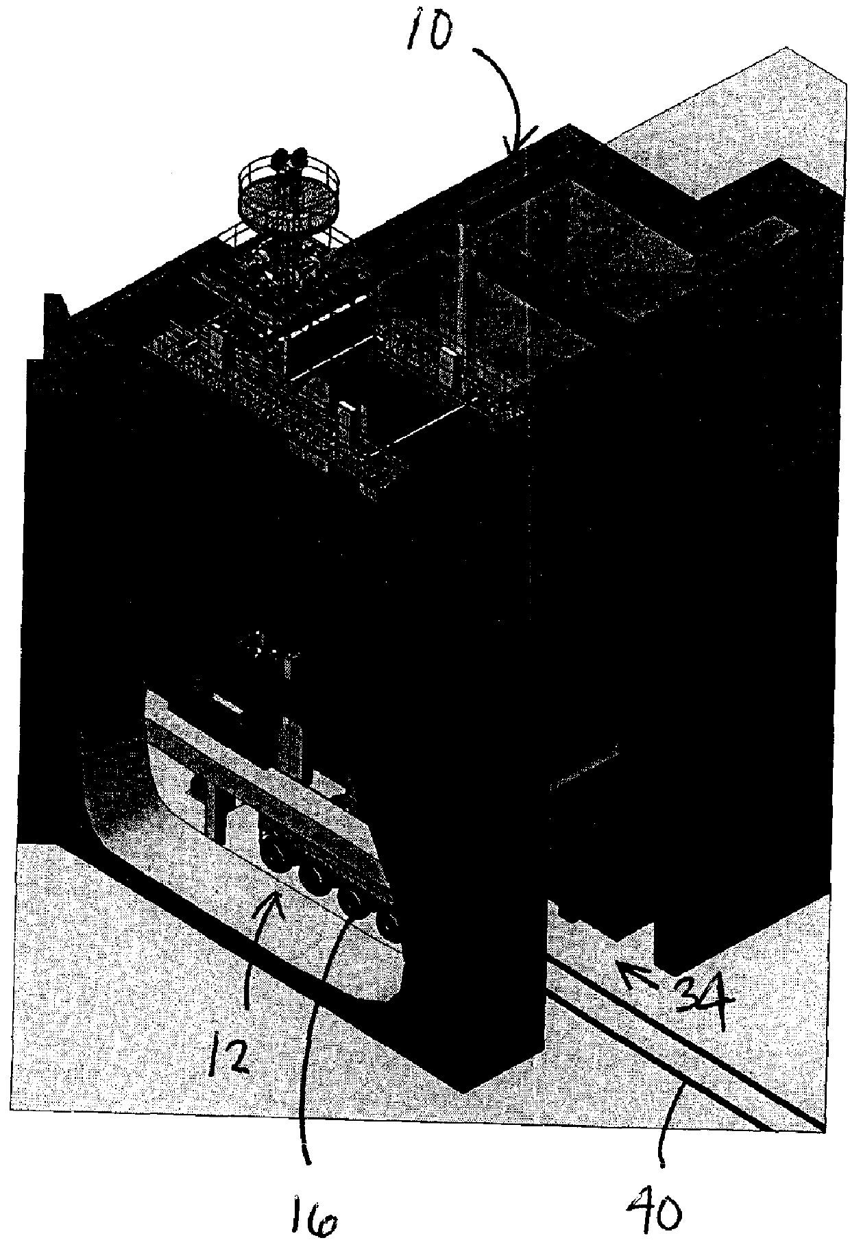
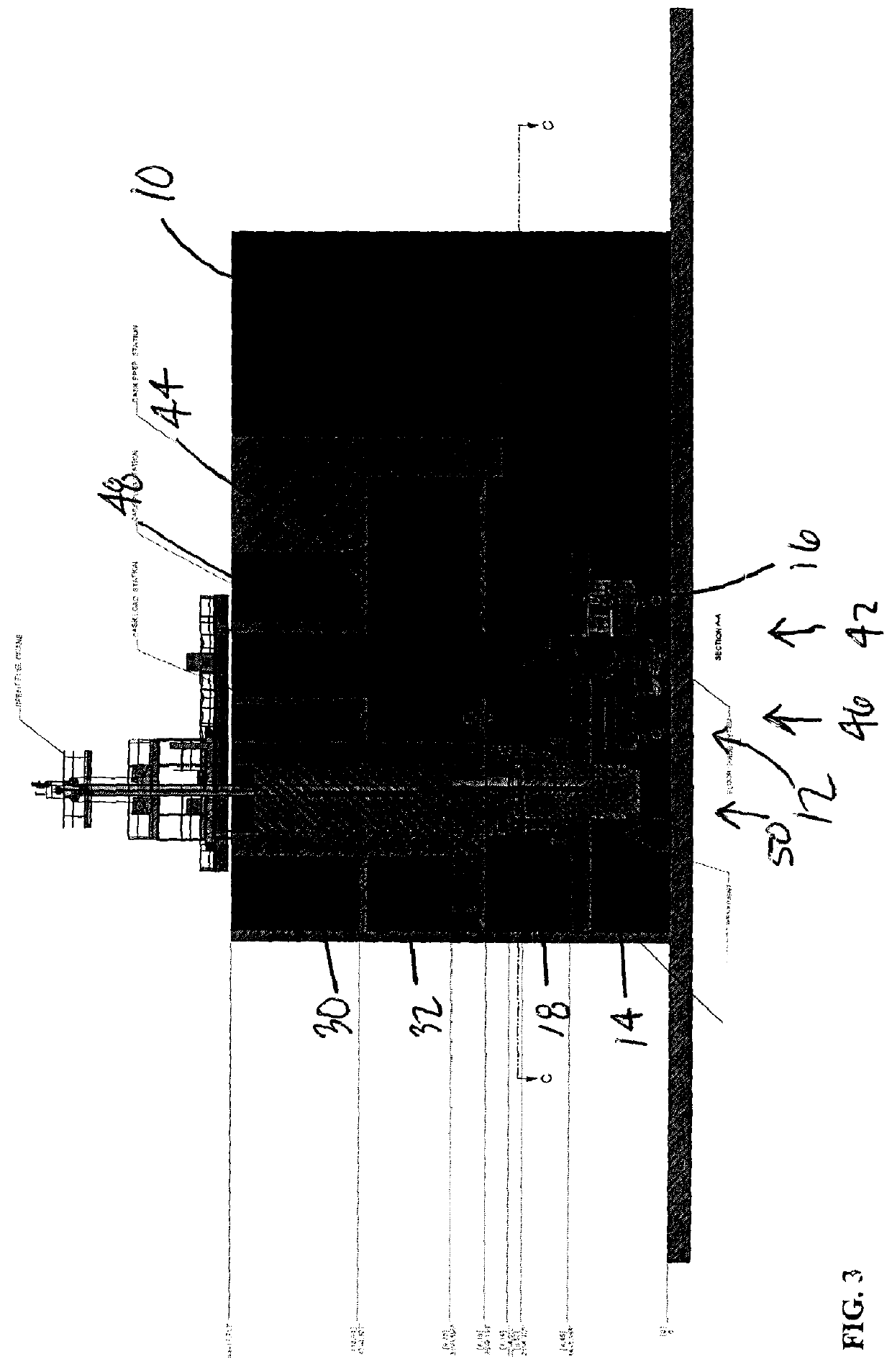
[0035]Referring now to the drawings, FIGS. 1 to 5 illustrate a fuel building 10 having a fuel transfer or cask handling system according to the present invention 12. The illustrated cask handling system 12 handles a spent fuel storage cask 14 through the process of removing spent nuclear fuel from the fuel building 10 including providing an unloaded cask 14, preparing and opening the cask 14, loading spent fuel into the cask 14, sealing the c...


PUM


Abstract

A system and method for removing spent fuel assemblies from a fuel building and transporting them to on-site facilities. A cask transporter is moved into the fuel building with an empty spent fuel storage cask, spent fuel assemblies are loaded into spent fuel storage cask, the cask is sealed, and the cask transporter moves the loaded spent fuel storage cask to a handling area for final disposal. Components of the system include a penetration cover, a lifting mechanism, a control system, a valve system, and the cask transporter.

Description

FIELD OF THE INVENTION[0001]The present invention generally relates to systems and methods for handling massive containers and, more particularly, handling storage casks for nuclear waste material.BACKGROUND OF THE INVENTION[0002]Nuclear power plants are required to have systems and methods for removing spent nuclear fuel from the plants so that it can be stored and / or processed. The spent nuclear fuel is typically stored in casks. While the current systems and methods may handle the casks, they have a number of problems. Existing systems have little documentation, require significant man hours, and use out-dated technology. These current methods also require a relatively large number of single use components that makes these systems expensive and difficult to maintain. Accordingly, there is a need in the art for improved systems and methods for handling casks containing nuclear waste material.SUMMARY OF THE INVENTION[0003]The present invention provides a system and method that over...

Claims


Application Information

Patent Timeline
Patent Type & Authority Applications(United States)
IPC IPC(8): G21F5/14B60P3/00B65G67/04
CPCG21F5/14G21C19/00G21C19/18G21C19/32Y02E30/30
Inventor WAISANEN, STEVEN K.YUSTUS, JOE
Owner MHE TECH
Why Eureka
Try Eureka