trampoline

a technology of trampoline and support rack, which is applied in the direction of rod connection, gymnastic exercise, fastening means, etc., to achieve the effects of enhancing evenly dispersing the stress, and increasing the physical strength of the circular support rack

Active Publication Date: 2013-02-21
CROWNTEC JIANG XI SPORTS TECH CO LTD
View PDF7 Cites 25 Cited by
  • Summary
  • Abstract
  • Description
  • Claims
  • Application Information

AI Technical Summary

Benefits of technology

[0011]In another embodiment of the invention the pad is surrounded by a plurality of connection rings, and each elastic member includes a first end fastened to the connection ring and a second end fastened to the circular support rack. The first and second support sections have respectively a connecting section connected to the first ridge. The first ridge may also be formed respectively on the upper side and lower side between the first and second support sections. In addition to the first ridge formed between the first and second support sections, the first support section further may have a second ridge and the second support section may have a third ridge to increase the physical strength of the first and second support sections. The second coupling end corresponding to the first coupling end has a first auxiliary support section corresponding to the first support section and a second auxiliary support section corresponding to the second support section, and a first auxiliary ridge corresponding to the first ridge. The first support tube further includes a branch tube to connect to a leg.
[0013]The present invention, by providing the ridge structure on the first coupling ends of the first and second support tubes can increase the physical strength of the circular support rack than the conventional frame made of circular tubes, and also can evenly disperse the stress withstood by the circular support rack to other portions. Furthermore, the bent tubes of the first and second support tubes have at least one groove indented inwards to further enhance the physical strength of the circular support rack to improve durability.

Problems solved by technology

In view of the conventional trampolines mostly have the frame made of circular tubes that have the problem of receiving uneven forces on the junctions and result in deformation.

Method used


Image

  • trampoline
  • trampoline
  • trampoline

Examples


Embodiment Construction

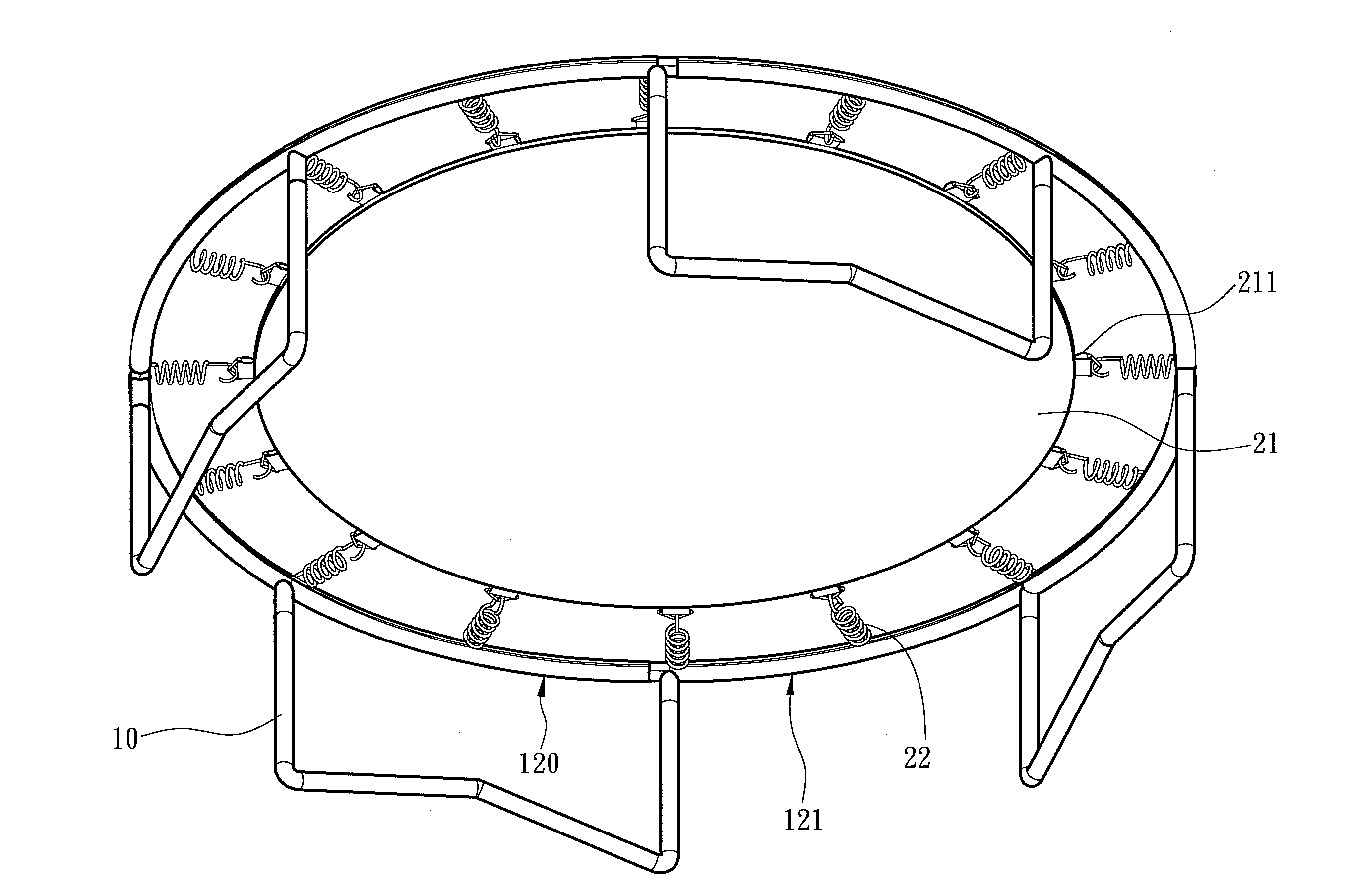
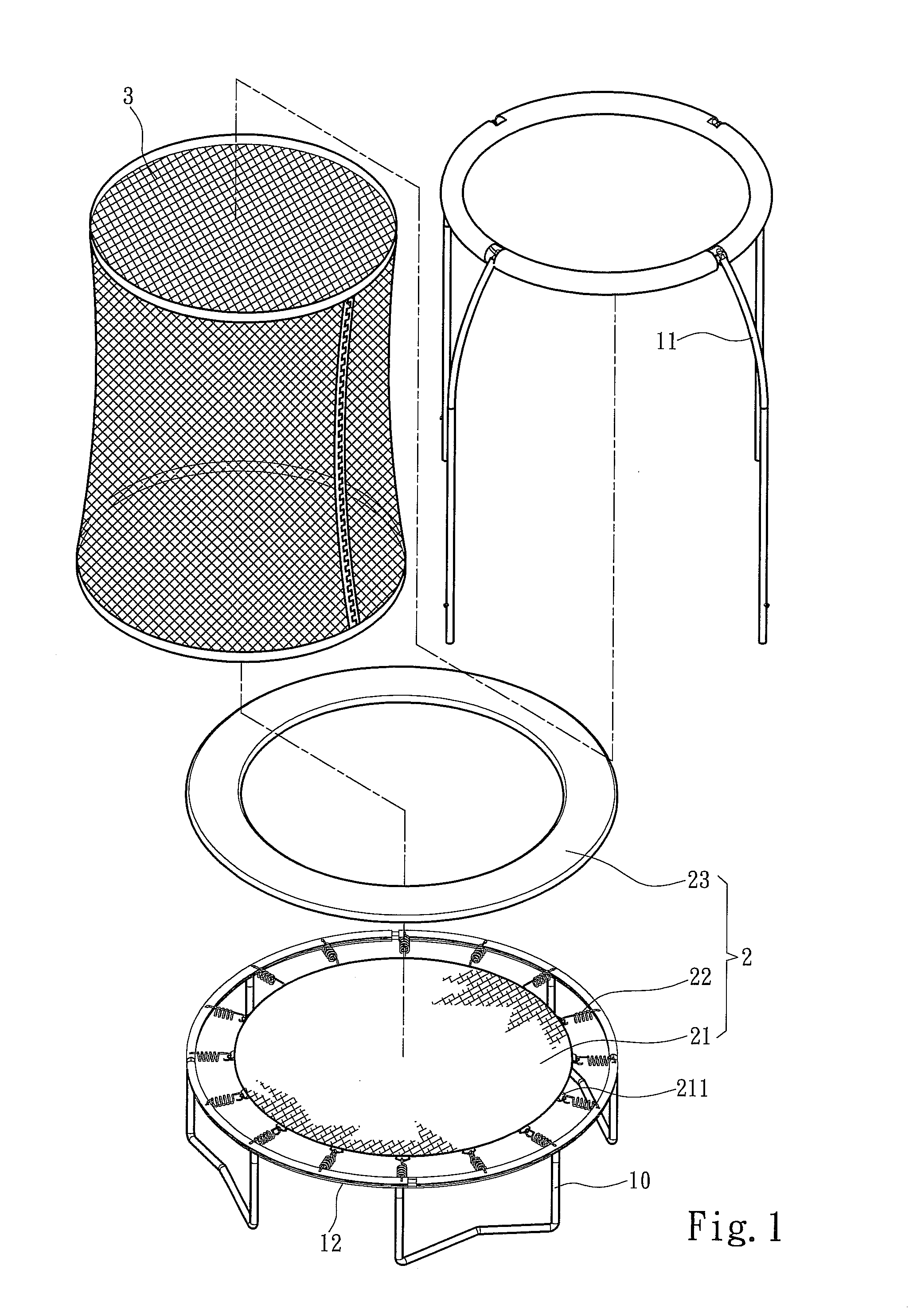
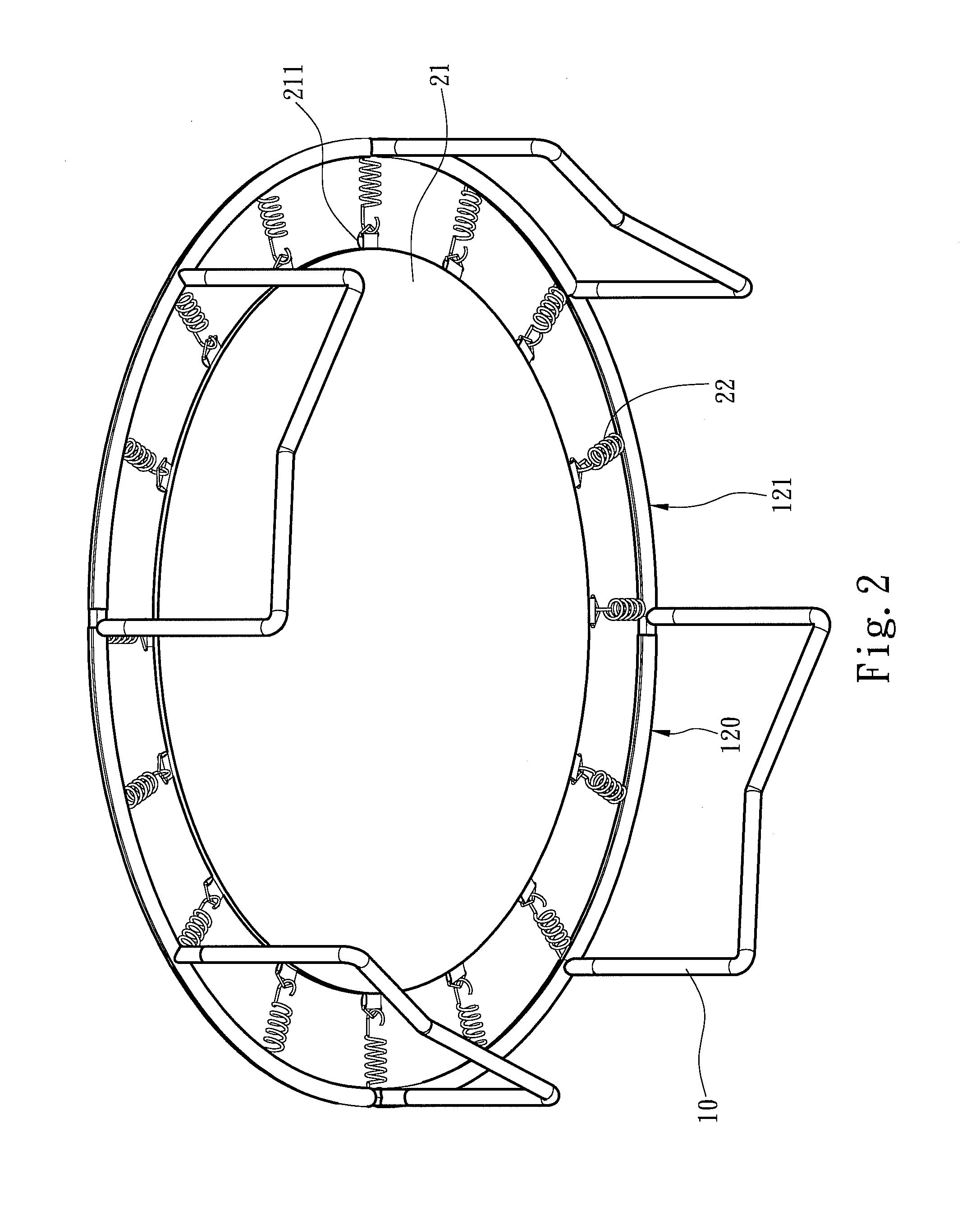
[0024]Please referring to FIGS. 1, 2 and 3, the present invention aims to provide a trampoline that includes a frame and a rebounding portion 2. In order to protect users the trampoline further has a guarding net 3 installed thereon. The frame includes a circular support rack 12 and a plurality of legs 10 supporting the circular support rack 12. The frame further has a plurality of support brackets 11 to hold and hang the guarding net 3 to facilitate installation thereof. Referring to FIG. 2, the rebounding portion 2 includes a pad 21 and a plurality of elastic members 22 on the circumference of the pad 21. The perimeter of the pad 21 also has a plurality of connection rings 211. Each elastic member 22 has a first end fastened to one connection ring 211 and a second end fastened to the circular support rack 12. Also referring to FIG. 1, to avoid users from falling into gaps between the elastic members 22 a protective mat 23 is provided to cover the gaps. The circular support rack 12...


PUM


Abstract

A trampoline includes a rebounding portion and a circular support rack. The rebounding portion includes a pad and a plurality of elastic members located on the circumference of the pad. The circular support rack is located around the rebounding portion and connected to the elastic members, and includes an inner ring side facing the rebounding portion and an outer ring side opposite to the inner ring side, and also includes at least one first support tube and one second support tube. The first support tube and second support tube have respectively a bent tube section, a first coupling end and a second coupling end corresponding to the first coupling end. The first coupling end includes a first support section located on the inner ring side, a second support section located on the outer ring side and at least one first ridge between the first and second support sections.

Description

FIELD OF THE INVENTION[0001]The present invention relates to a trampoline and particularly to a trampoline with greater durability.BACKGROUND OF THE INVENTION[0002]Affluent people of modern time have greater awareness on life quality enhancing activities such as leisure activities and exercises. Many people these days lack enough exercises and exercise space. To overcome these constraints many exercise equipments and fitness facilities have been developed that take smaller space and are simple in use.[0003]For instance U.S. Pat. No. 7,766,795 discloses a trampoline system which includes a circular frame supported by a plurality of legs. The circular frame is coupled with a rebounding mat through a plurality of spring members and a cylindrical wall made of a resilient net to prevent users from being thrown outside the trampoline when in use. When a user jumps and rebounds from the mat the spring members are stretched by the weight of the user and mat. The spring members have other en...

Claims


Application Information

Patent Timeline
Patent Type & Authority Applications(United States)
IPC IPC(8): A63B5/11
CPCA63B5/11F16B7/042A63B21/023A63B2071/009A63B2210/50A63B71/022
Inventor HSIANG, HUA-LU
Owner CROWNTEC JIANG XI SPORTS TECH CO LTD
Why Eureka
Try Eureka