Eureka AIR delivers breakthrough ideas for toughest innovation challenges, trusted by R&D personnel around the world.

Non-aqueous electrolyte secondary cell

a secondary cell, non-aqueous electrolyte technology, applied in secondary cell servicing/maintenance, cell components, cell component details, etc., can solve the problem of not giving enough, certain time lag until the separator pores are completely blocked, and the approach cannot be said to give enough, etc. problem, to achieve the effect of improving the low temperature characteristics, not stopping up in a short time, and superior shutdown effects

Inactive Publication Date: 2006-10-05
MURATA MFG CO LTD
View PDF8 Cites 25 Cited by
  • Summary
  • Abstract
  • Description
  • Claims
  • Application Information

AI Technical Summary

Benefits of technology

[0015] It is therefore an object of the present invention to provide a non-aqueous electrolyte secondary cell which has achieved both the optimum low temperature characteristics and high safety against over-charging simultaneously.
[0016] It is another object of the present invention to provide a non-aqueous electrolyte cell in which temperature rise at the time of an unusual cell operation is suppressed and which makes it possible to maintain optimum productivity.
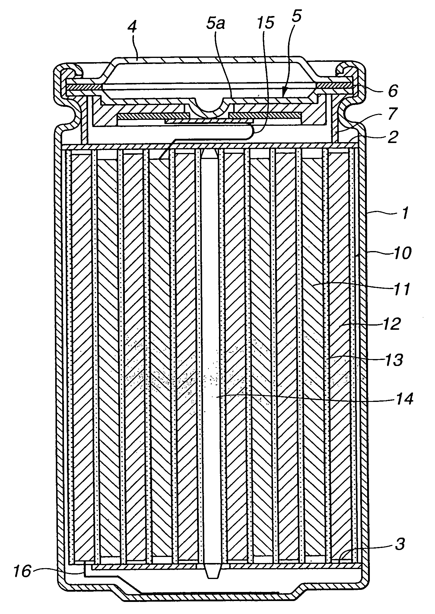
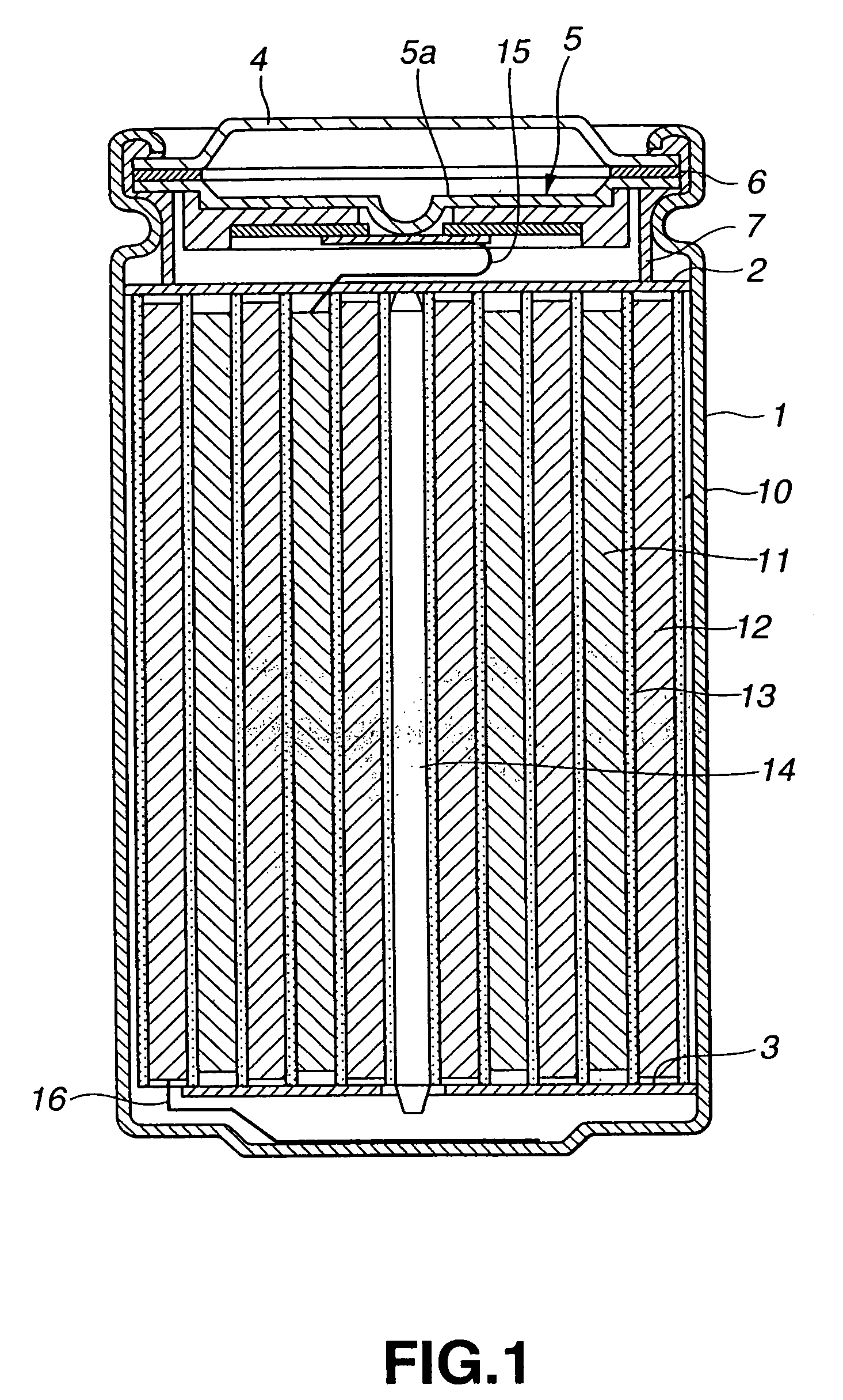
[0037] In the non-aqueous electrolyte secondary cell of the present invention, as described above, in which the average pore diameter of the micro-sized pores of the layer having the highest porosity is of a larger value, the ionic conductivity across the cathode and the anode in charging / discharging may be optimized, thus improving low temperature characteristics. Moreover, the average pore diameter of the micro-sized pores of the layer having the lowest porosity is of a smaller value, the micro-sized pores are not stopped up in a short time even when the inner temperature in the non-aqueous electrolyte secondary cell is raised due to overcharging, thus assuring superior shutdown effects and high safety against overcharging.
[0038] Thus, with the non-aqueous electrolyte secondary cell of the present invention, both the optimum low temperature characteristics and high safety against overcharging may be achieved in combination.
[0039] Also, with the non-aqueous electrolyte secondary cell of the present invention, the micro-porous film among the plural micro-porous films of the separator which is proximate to the cathode has a lower melting point. Thus, the micro-porous film proximate to the cathode promptly absorbs the heat generated in the cathode in case of an unusual cell operation to suppress temperature rise in the cell. On the other hand, the micro-porous film or films other than the micro-porous film proximate to the cathode is of a higher melting point and hence has a high physical strength. Consequently, with the non-aqueous electrolyte secondary cell of the present invention, temperature rise in case of the unusual cell operation may be suppressed to assure high safety against overcharging, while high productivity is assured.

Problems solved by technology

Thus, if a polyolefin based porous film, liable to be torn, is built into the lithium cell as a separator for the cell, there is a risk that the film is damaged by the micro-irregularities on the plate surface to cause electrical shorting.
Although it has been proposed to use two sorts of porous films having different values of mechanical strength to improve the film strength, this approach cannot be said to give sufficient results.
However, when the value of the porosity of the separator, comprised of a polyolefin micro-porous film, is high, there is a certain time lag until separator pores are completely blocked since the separation reaches the shutdown temperature.
In such case, there is a possibility of electrical shorting in the non-aqueous electrolyte secondary cell due to physical contact between the cathode and the anode.
However, in this case, lithium ions are hardly movable across the cathode and the anode during charging / discharging of the non-aqueous electrolyte secondary cell, with the result that its low temperature characteristics are deteriorated.
Thus, there has as yet not been established a non-aqueous electrolyte secondary cell having optimum low temperature characteristics and high safety against over-charging.
On the other hand, if a micro-sized-pore polyolefin film having a low melting point is used as a separator, it is poor in physical strength against e.g., punching, piercing, thus raising the inferiority fraction in manufacturing the cells.

Method used


Image

  • Non-aqueous electrolyte secondary cell
  • Non-aqueous electrolyte secondary cell
  • Non-aqueous electrolyte secondary cell

Examples


experiment 3

[0270] The desirable thickness of the cathode side micro-porous film, with respect to the total separator thickness, was then scrutinized.

Sample 42

[0271] A non-aqueous electrolyte secondary cell was prepared in the same way as in sample 30, except using, as a first layer micro-porous film, a film of micro-porous polyethylene, with melting points of 125° and 135° C., a thickness of 4 μm and a porosity of 36%, and also using, as a second layer micro-porous film, a film of micro-porous polyethylene, with the melting point of 135° C., a thickness of 30 μm and a porosity of 36%. Meanwhile, the thickness of the cathode side micro-porous film with respect to the total separator thickness was 11.8%.

Sample 43

[0272] A non-aqueous electrolyte secondary cell was prepared in the same way as in sample 30, except using, as a first layer micro-porous film, a film of micro-porous polyethylene, with melting points of 125° and 135° C., a thickness of 7 μm and a porosity of 36%, and also using, a...

experiment 4

[0283] The desirable range of the melting point of the side cathode micro-porous film forming the separator was then scrutinized.

Sample 50

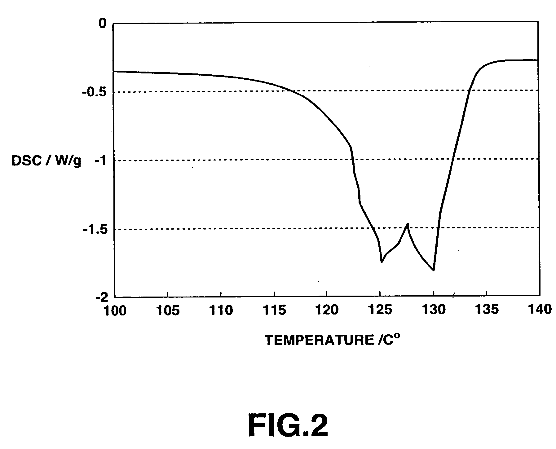
[0284] A non-aqueous electrolyte secondary cell was prepared in the same way as in sample 30, except using, as a first layer micro-porous film, a film of micro-porous polyethylene, with melting points of 125° and 135° C., a thickness of 7 μm and a porosity of 36%, and also using, as a second layer micro-porous film, a film of micro-porous polyethylene, with the melting point of 135° C., a thickness of 27 μm and a porosity of 36%.

Sample 51

[0285] A non-aqueous electrolyte secondary cell was prepared in the same way as in sample 30, except using, as a first layer micro-porous film, a film of micro-porous polyethylene, with melting points of 122° and 130° C., a thickness of 7 μm and a porosity of 36%, and also using, as a second layer micro-porous film, a film of micro-porous polyethylene, with the melting point of 135° C., a thickness of 27 μm ...

experiment 5

[0294] The desirable value of the porosity of the separator was then investigated.

Sample 57

[0295] A non-aqueous electrolyte secondary cell was prepared in the same way as in sample 30, except using, as a first layer micro-porous film, a film of micro-porous polyethylene, with melting points of 125° and 130° C., a thickness of 17 μm and a porosity of 20%, and also using, as a second layer micro-porous film, a film of micro-porous polyethylene, with the melting point of 135° C., a thickness of 17 μm and a porosity of 20%.

Sample 58

[0296] A non-aqueous electrolyte secondary cell was prepared in the same way as in sample 30, except using, as a first layer micro-porous film, a film of micro-porous polyethylene, with melting points of 125° and 130° C., a thickness of 17 μm and a porosity of 25%, and also using, as a second layer micro-porous film, a film of micro-porous polyethylene, with the melting point of 135° C., a thickness of 17 μm and a porosity of 25%.

Sample 59

[0297] A no...


PUM

PropertyMeasurementUnit
porosityaaaaaaaaaa
porosityaaaaaaaaaa
porosityaaaaaaaaaa

Abstract

A non-aqueous electrolyte secondary cell which achieves satisfactory low temperature characteristics and high safety against overcharging in combination. The cell includes a lithium-containing cathode, an anode capable of doping and undoping lithium, a non-aqueous electrolyte and a separator. The separator is made up by a plurality of layers of a porous material or materials presenting micro-sized pores. The layers of the porous material or materials is formed of micro-porous separator materials representing different combinations of the porosity, melting point or material / compositions.

Description

BACKGROUND OF THE INVENTION [0001] 1. Field of the Invention [0002] This invention relates to a non-aqueous electrolyte secondary cell having a cathode, an anode, a non-aqueous electrolyte and a separator. More particularly, it relates to a non-aqueous electrolyte secondary cell in which a separator is of a multi-layer structure having two or more layers. [0003] 2. Description of Related Art [0004] Recently, variegated portable electronic equipment, such as camera built-in type VTR (video tape recorder), portable telephone sets or lap top computers, have made their debut and, with remarkable progress in the electronic technology, small-sized lightweight versions of these electronic equipment have been realized one after another. As a portable power supply for these electronic equipment, researches and developments for improving the energy density of the cells, in particular the secondary cells, as portable power sources for these electronic equipment, are going on briskly. [0005] Of...

Claims


Application Information

Patent Timeline
Patent Type & Authority Applications(United States)
IPC IPC(8): H01M2/16H01M4/58H01M10/50H01M6/10H01M10/0525H01M10/36H01M10/42H01M50/417H01M50/426H01M50/457H01M50/491
CPCH01M2/1653H01M2/1686H01M2/348Y02E60/122H01M10/0525H01M10/4235H01M6/10Y02E60/10H01M50/581H01M50/417H01M50/457H01M50/491H01M50/426
Inventor YAMAGUCHI, AKIRAOMARU, ATSUONAGAMINE, MASAYUKI
Owner MURATA MFG CO LTD
Why Eureka
Eureka Blog
Learn More