Working vehicle

a technology for working vehicles and drive units, applied in the direction of electric propulsion mounting, transportation and packaging, jet propulsion mounting, etc., can solve the problems of sudden acceleration inhibited, the upper portion of the engine being displaced, and the drive unit vibrating

Active Publication Date: 2013-02-28
KUBOTA LTD
View PDF8 Cites 13 Cited by
  • Summary
  • Abstract
  • Description
  • Claims
  • Application Information

AI Technical Summary

Benefits of technology

[0012]A purpose of the present invention is to reasonably configure a working vehicle in which lateral vi

Problems solved by technology

Thereby, even when traveling on rough terrain and the like, a phenomenon is inhibited in which the drive unit vibrates greatly, and disadvantageous large displacement of the upper portion of the engine in jump landing, sharp cornering, and sudden acceleration is inhibited.[Related Art 1] Japanese Patent Laid-Open Publication No. 2006-27466
In such a configuration, a side of the drive unit that corresponds to the other one of the upper pipes is allowed to be displaced, and thus the drive unit may easily

Method used


Image

  • Working vehicle
  • Working vehicle
  • Working vehicle

Examples


Embodiment Construction

[0039]The particulars shown herein are by way of example and for purposes of illustrative discussion of the embodiments of the present invention only and are presented in the cause of providing what is believed to be the most useful and readily understood description of the principles and conceptual aspects of the present invention. In this regard, no attempt is made to show structural details of the present invention in more detail than is necessary for the fundamental understanding of the present invention, the description is taken with the drawings making apparent to those skilled in the art how the forms of the present invention may be embodied in practice.

[0040]In the following, an embodiment of the present invention is explained based on the drawings.

(Overall Configuration)

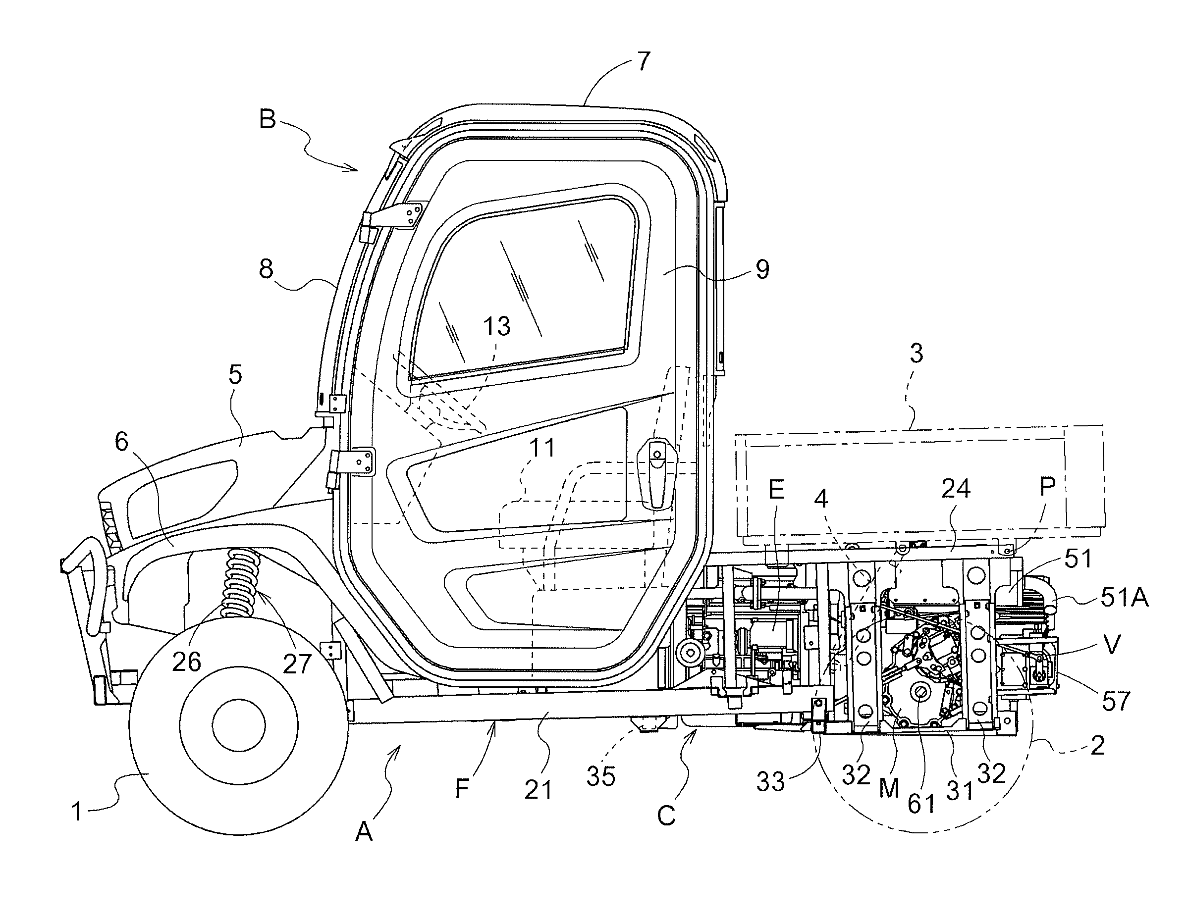
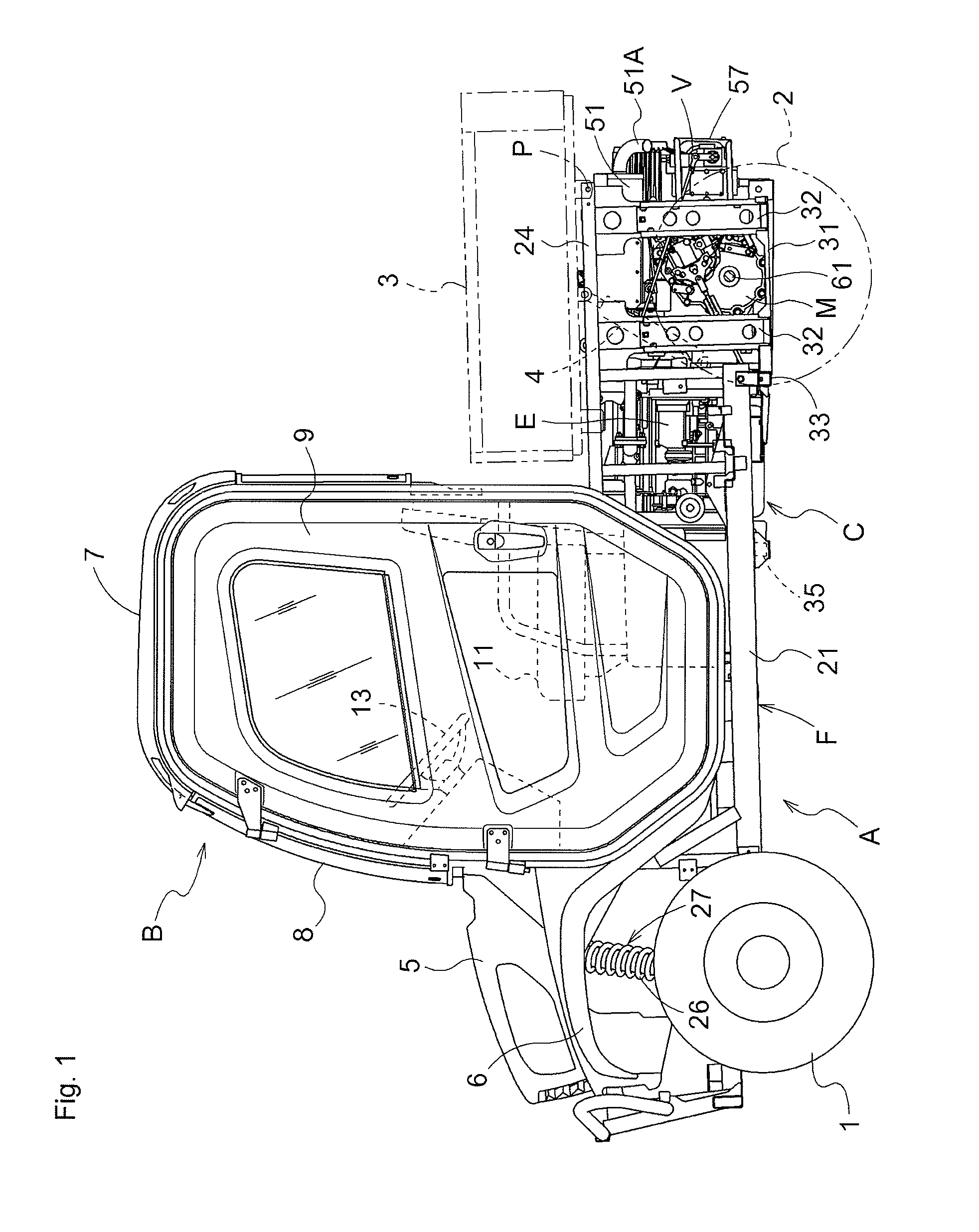
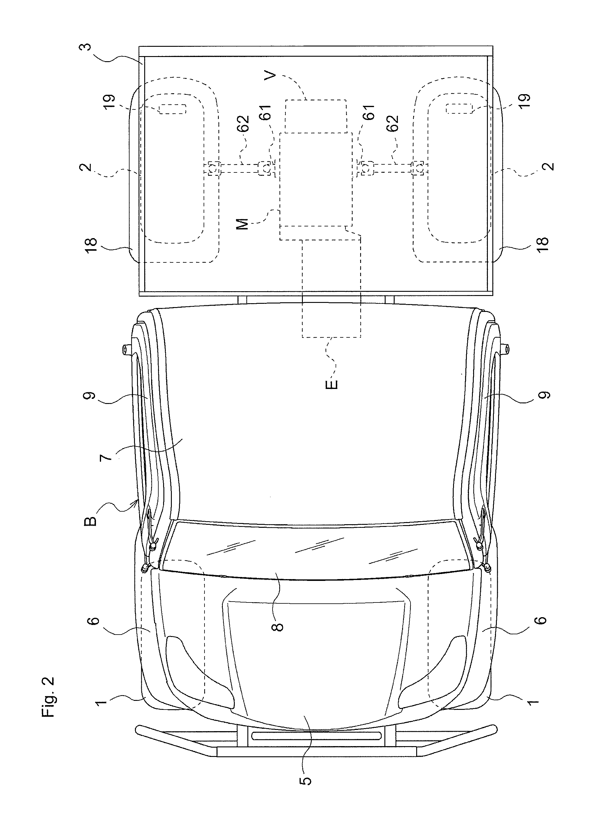
[0041]As FIGS. 1-3 illustrate, a working vehicle is configured in which a traveling vehicle body A is provided with a pair of freely steerable left and right front wheels 1 and a pair of left and right rear ...


PUM


Abstract

An engine and a transmission case are connected to configure a drive unit. Left and right lower portions of the engine and left and right lower portions of the transmission case are supported on an underframe by lower anti-vibration mounts. A lateral frame is provided in a form bridging left and right upper frames. An upper portion of the transmission case is supported by an upper anti-vibration mount on a middle portion of the lateral frame.

Description

CROSS-REFERENCE TO RELATED APPLICATIONS[0001]The present application claims priority under 35 U.S.C. §119 of Japanese Application No. 2011-180915, filed on Aug. 22, 2011, the disclosure of which is expressly incorporated by reference herein in its entirety.BACKGROUND OF THE INVENTION[0002]1. Field of the Invention[0003]The present invention relates to a working vehicle in which a drive unit is arranged at a rear position of a traveling vehicle body. More specifically, the present invention relates to a configuration supporting the drive unit.[0004]2. Description of Related Art[0005]As a configuration supporting a drive unit in a working vehicle, Related Art 1 discloses a configuration in which a vehicle body frame is configured to include a pair of left and right upper pipes and a pair of left and right lower pipes; a bottom portion of a drive unit (referred to as an “engine unit” in Related Art 1), which is configured from an engine and a transmission, is supported in an anti-vibra...

Claims


Application Information

Patent Timeline
IPC IPC(8): B62D63/02B62D63/04B60K5/12
CPCB60K5/02B60K5/1216B60K13/04B60Y2200/141B60K17/22B60K17/34B60K17/10
Inventor KURAMOTO, TAKASHI
Owner KUBOTA LTD
Why Eureka
Try Eureka