Threaded adaptor

a threaded adaptor and threaded technology, applied in the direction of hose connection, pipe-joint, fluid pressure sealing joint, etc., can solve the problems of limited opportunity for connecting adjacent hoses and difficulty in providing threaded adaptors, and achieve the effect of low manufacturing cos

Active Publication Date: 2013-02-28
HUSKY
View PDF5 Cites 5 Cited by
  • Summary
  • Abstract
  • Description
  • Claims
  • Application Information

AI Technical Summary

Benefits of technology

[0017]Another object is to provide such an adaptor that has a low cost of manufacturing so the purchasing people and organizations can readily buy the adaptor through stores and supply sources.

Problems solved by technology

The difficulty in providing a threaded adaptor is also shown by the existing adaptors.
The prior art adaptors provide limited opportunity to connect adjacent hoses in the absence of a rotation preventing object.

Method used


Image

  • Threaded adaptor
  • Threaded adaptor
  • Threaded adaptor

Examples


second embodiment

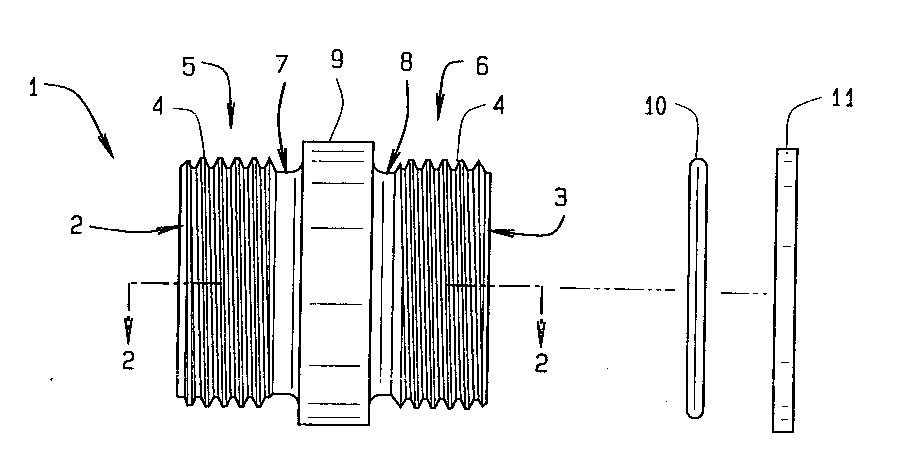
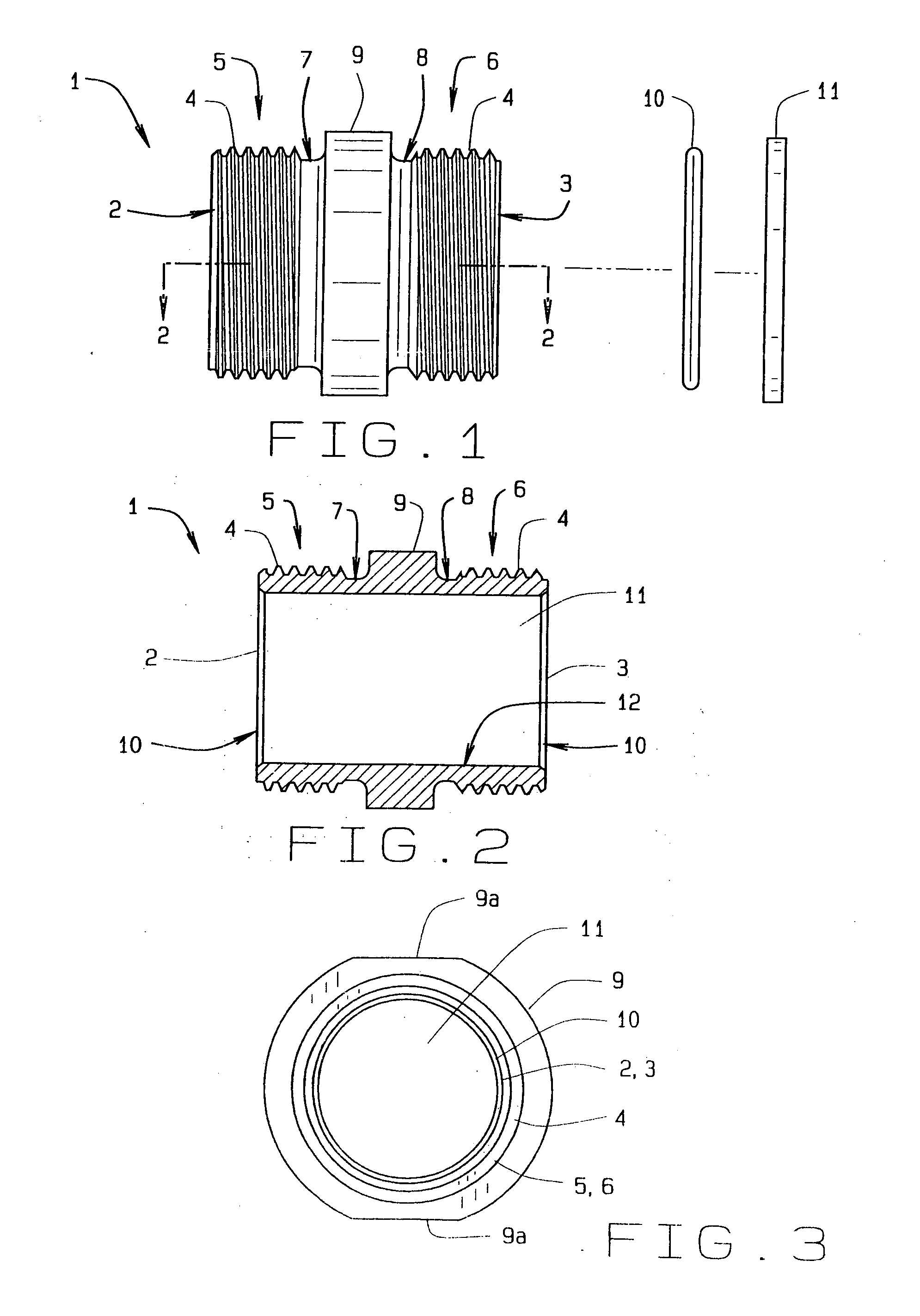
[0047]the adaptor appears in FIG. 7 in a side view. This adaptor 1 also has a generally hollow cylindrical form with a first end 2 and an opposite second end 3. As shown both ends 2, 3, have external threads here shown as right hand. The threads continued for approximately five revolutions around the circumference of the ends. The threads extend inwardly upon a first stem 5 and an opposite second stem 6. The stems are hollow and have sufficient length for a solid connection of the adaptor to a hose or other fitting. The threads upon the first stem, as at 4, have generally coarse form while the threads upon the second stem, as at 4a, have generally fine form. Inwardly, each stem has a notch, a first notch 7 at the interior ending of the threads 4 on the first stem 5. The second stem 6 also has a flange 15 inwardly of the interior ending of the threads 4a and a second notch 8 inwardly of the flange opposite the first notch where the threads 4 end on the second stem 6. The notches 7, 8...

third embodiment

[0051]the adaptor appears in FIG. 11 in a side view. This adaptor 1 also has a generally hollow cylindrical form with a first end 2 and an opposite second end 3. As shown, the end 2 has external threads here shown as right hand, that continue for approximately five revolutions around the circumference of the end. The threads extend inwardly upon a first stem 5 but not an opposite second stem 18. The stems are hollow and have sufficient length for a solid connection of the adaptor to a hose or other fitting. The threads upon the first stem, as at 4, have generally coarse form. However, the second stem 18 has generally three concentric barbs 19 extending inwardly from the second end 3. The barbs have an angled shape parallel to the length of the adaptor, in this view, where the narrowest diameter of a barb locates towards the end 3 while the wider diameter locates towards the collar 9. Inwardly, the first stem 5 has the first notch 7 at the interior ending of the threads 4, proximate ...


PUM


Abstract

A threaded adaptor has a first end and an opposite second end of a generally hollow cylinder. At least one end has threading for connection to a hose or fitting and the ends form the male half of the connection. Centered upon the adaptor, a collar provides at least two faces for gripping of the adaptor by a tool. Within the adaptor, the two ends open into a smooth chamber that allows for uninterrupted fluid flow. To further seal the adaptor, at least one O-ring and at least one gasket are provided as alternate embodiments. In another alternate embodiment, the adaptor has one threaded end, an opposite barbed end with a clamp, and a collar with six faces. These two ends open into a chamber with a stepped diameter. The adaptor provides for flow of fluid with little turbulence.

Description

BACKGROUND OF THE INVENTION[0001]This threaded adaptor relates in general to means for connecting coaxial hoses, nozzles, and fittings, such as a gasoline line connecting to a nozzle used by motorists for fuel dispensing at a service station, and more specifically to improvements upon the adaptor for grasping by a tool, a straight flow path, and either an O-ring or gasket upon each end of the adaptor for sealing. A unique aspect of the present adaptor is its single piece body that provides for a cylindrical flow path through the interior of the adaptor.[0002]Upon arriving at a pump of a service station, a motorist views a nozzle connected to a length of hose, and the hose connected to the pump. The lengths of hose, fittings, and nozzles require connection among themselves and to service station pumping facilities. Hoses extend from fixed and rigid piping extending from the pump, generally concealed from a motorist. The hoses may extend from the side of the pump, approximately midway...

Claims


Application Information

Patent Timeline
Patent Type & Authority Applications(United States)
IPC IPC(8): F16L33/24F16L15/04F16L15/08F16L15/00
CPCF16L15/04F16L33/2071F16L25/14
Inventor WOLFF, BRIAN P.
Owner HUSKY
Why Eureka
Try Eureka