Lens shape measurement device

a technology of shape measurement and lens, applied in the direction of measurement devices, geometric properties/aberration measurement, instruments, etc., can solve the problem of inability to adjust the spectacle, and achieve the effect of accurate measurement and further efficient measuremen

Inactive Publication Date: 2013-02-28
HOYA CORP
View PDF5 Cites 21 Cited by
  • Summary
  • Abstract
  • Description
  • Claims
  • Application Information

AI Technical Summary

Benefits of technology

[0041]According to the present invention, even in a case that the lens edge is edged into a mirror surface, etc., the dimension and the shape of the lens can be accurately measured using the laser displacement meter.
[0042]Further, when an edged shape of the lens is already known, the dimension and the shape of the lens can be further efficiently measured.

Problems solved by technology

However, when an edging error in the lens shape by this device exceeds an allowable range, there is a possibility that inconveniences are invited such that the edged lens cannot be framed into the spectacle frame, or in a case of the rimless frame, a spectacle cannot be adjusted by assembling it into frame components.

Method used


Image

  • Lens shape measurement device
  • Lens shape measurement device
  • Lens shape measurement device

Examples


Embodiment Construction

[0058]Embodiments of the present invention will be described in detail hereafter, with reference to the drawings.

1. Structure of a Lens Shape Measurement Device

[0059](Structure of a Mechanism System)

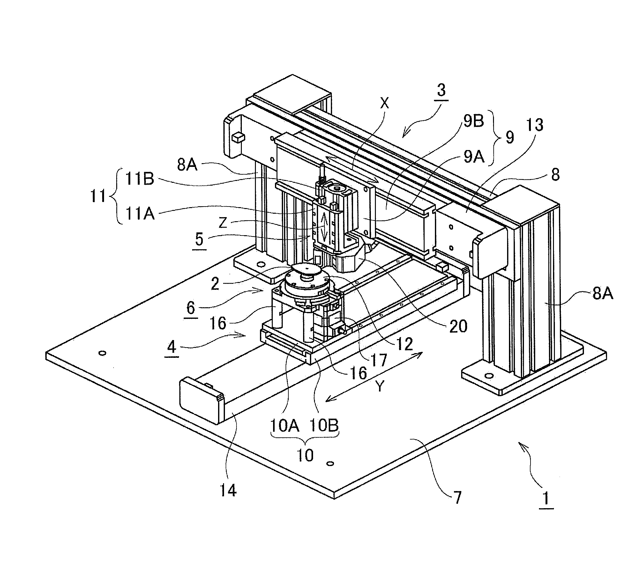
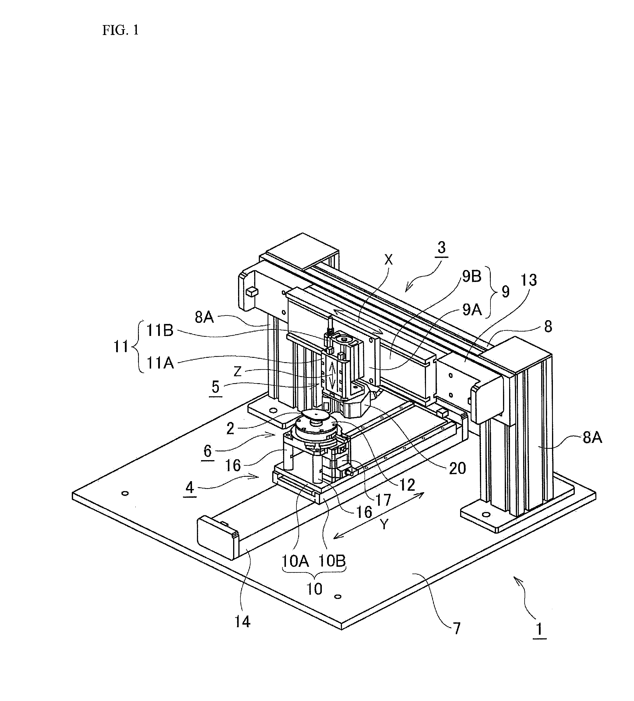
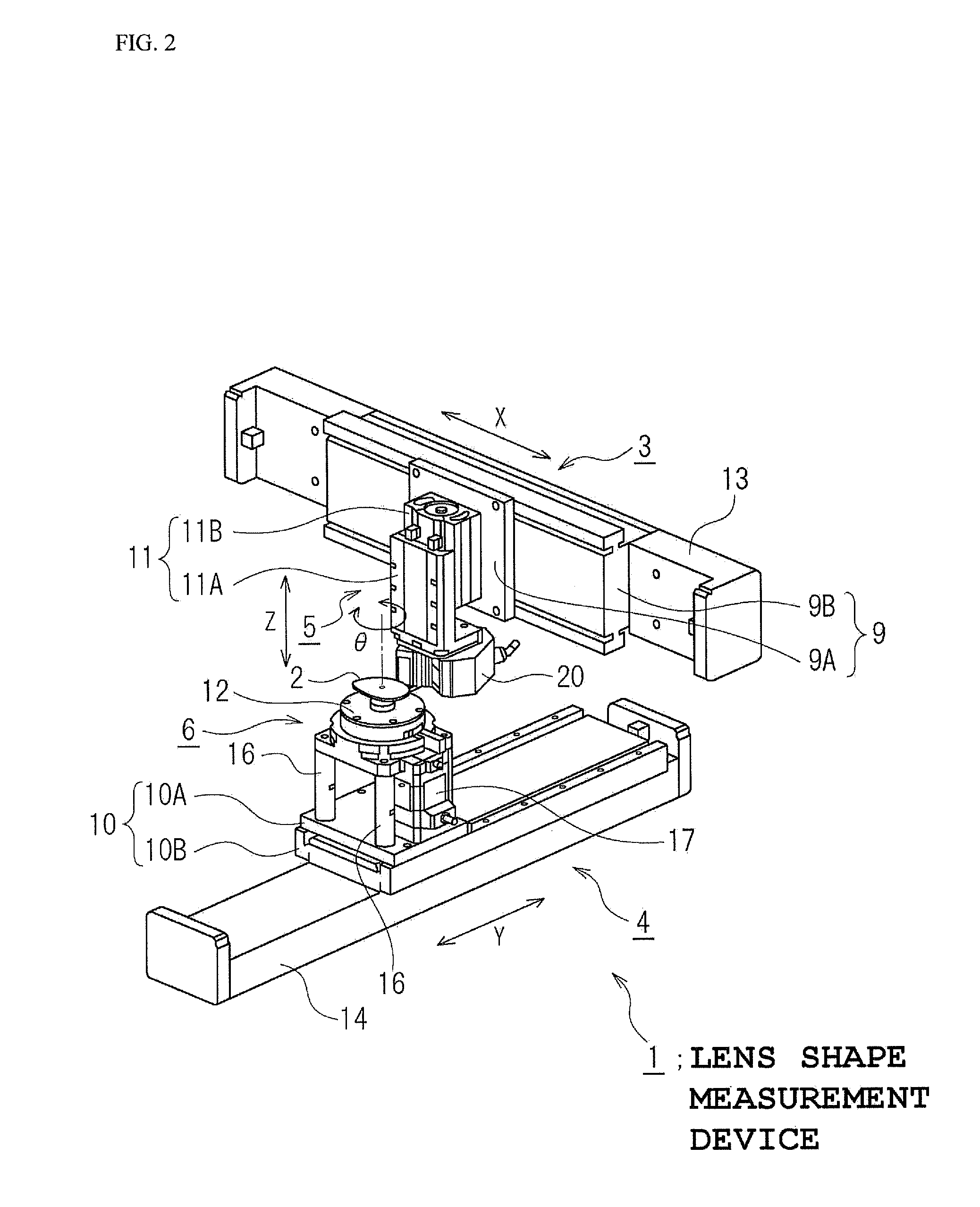
[0060]FIG. 1 is a perspective view of a constitutional example of a lens shape measurement device according to an embodiment of the present invention, and FIG. 2 is a perspective view extracting a part of the lens shape measurement device. Note that in FIG. 1 and FIG. 2, a width direction (right and left direction) of the lens shape measurement device is set as a X-direction (also described as “X-axis direction” hereafter), and a depth direction of the lens shape measurement device is set as a Y-direction (also described as “Y-axis direction” hereafter), and a height direction (upper and lower direction) of the lens shape measurement device is set as a Z-direction (also described as “Z-axis direction” hereafter). In the description hereafter, an axis parallel to the X-direction is set as...


PUM


Abstract

A lens shape measurement device, includes: a rotation unit that rotates a lens supported by a stage; a laser displacement meter; a first moving unit that moves the laser displacement meter in a X-direction; a second moving unit that moves the lens in a Y-direction; and a drive controller that controls a drive of the rotation unit, the first moving unit, and the second moving unit in a mirror reflection state in which an incidence angle of the laser beams incident on a measurement target from the laser displacement meter, and a reflection angle of the laser beams reflected by the measurement target are equal to each other with a normal line of the lens passing through the measurement target set as a reference, for each of a plurality of measurement targets set on an edge of the lens in a rotating direction of the lens.

Description

TECHNICAL FIELD[0001]The present invention relates to a lens shape measurement device.DESCRIPTION OF RELATED ART[0002]In order to frame a prescribed spectacle lens into a spectacle frame, an uncut lens (non-edged lens) such as a circular or an oval lens supplied from a lens manufacturer, is subjected to lens edging (called a edging hereafter) , so as to match a lens frame shape (lens shape) of the spectacle frame. The lens shape is different depending on a design of a frame, and the edging is different depending on a type of the frame. The spectacle frame is roughly classified into a rimless frame and a rim frame (called a full rim frame hereafter). A V-shaped bevel groove is formed on the lens frame of the full rim frame, so that a framed lens is subjected to the edging so as to correspond to its rim shape.[0003]Meanwhile, in the spectacle lens which is subjected to edging so as to match a normal rimless frame, a side surface of a spectacle lens (edge) is flat having no bevel groov...

Claims


Application Information

Patent Timeline
Patent Type & Authority Applications(United States)
IPC IPC(8): G01B11/24
CPCG01M11/025G01B11/24
Inventor SAMUKAWA, MASAHIKODAIMARU, TAKASHITAKEDA, NOBUHIKO
Owner HOYA CORP
Why Eureka
Try Eureka