

Optical image capturing lenses
a technology of optical image and lens, applied in the field of optical image capture lenses, can solve the problems of inability to produce high-quality images, insufficient degree of freedom in setting system parameters, and the length of the total optical track of the lens structur
- Summary
- Abstract
- Description
- Claims
- Application Information
AI Technical Summary
Benefits of technology
Problems solved by technology
Method used
Image

Examples
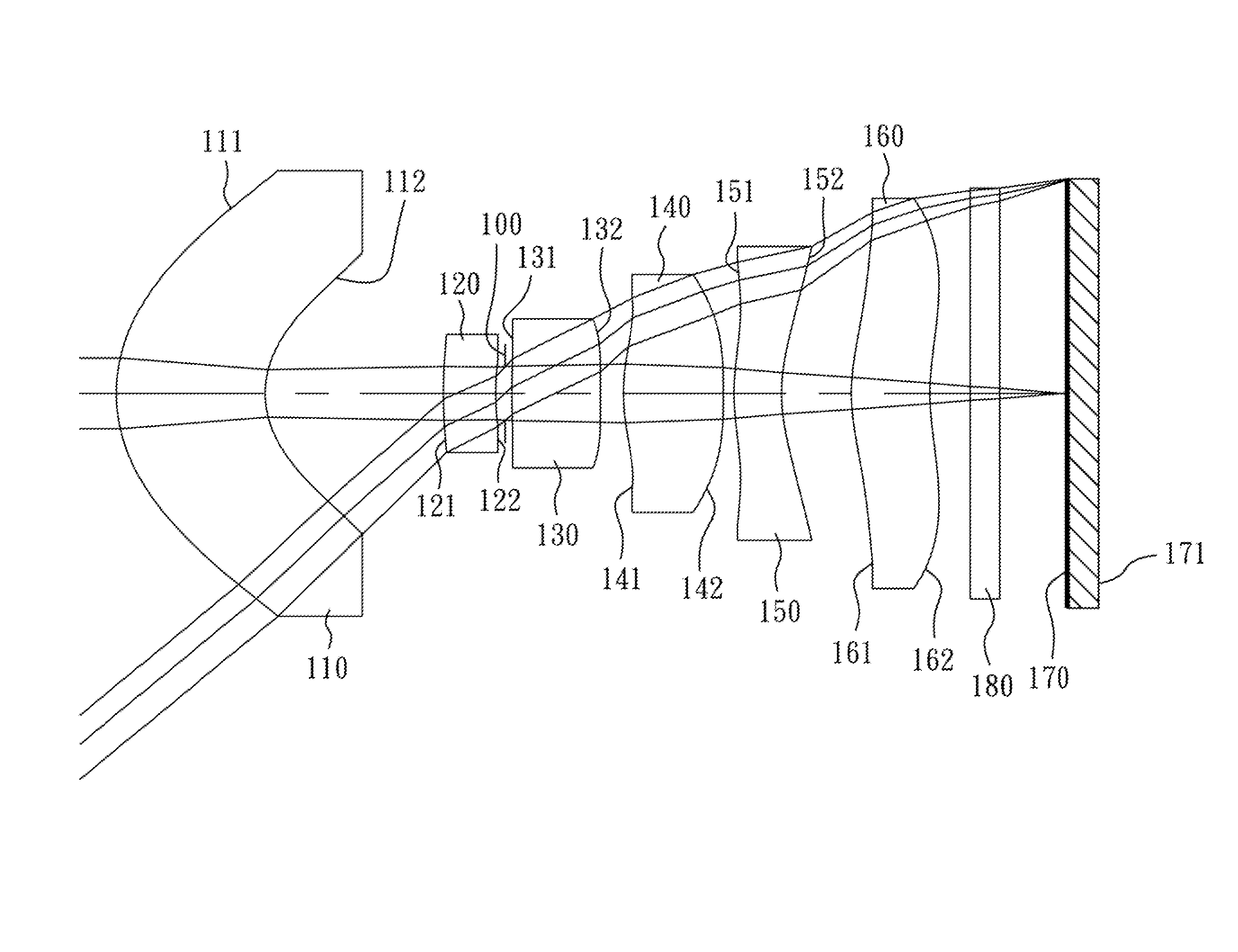
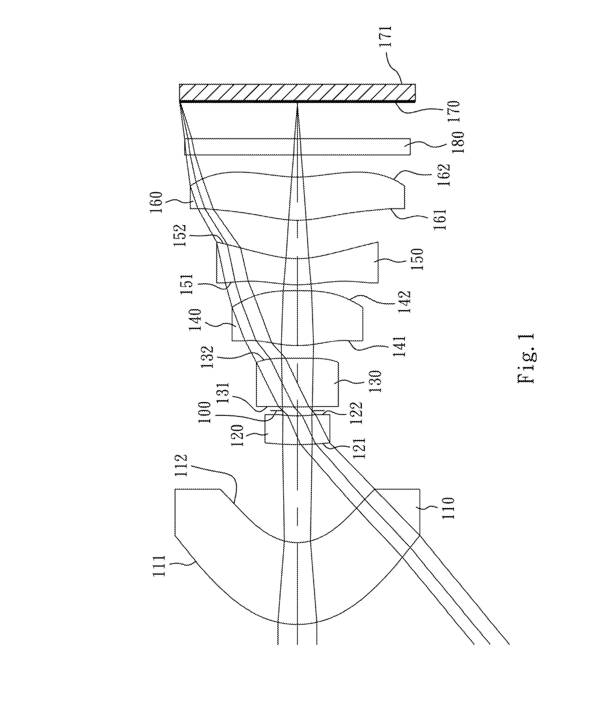
first embodiment
[0058]The equation of the aspheric surface profiles of the aforementioned lens elements of the first embodiment is expressed as follows:
X(Y)=(Y2 / R) / (1+sqrt(1-(1+k)×(Y / R)2))+∑i(Ai)×(Yi)
[0059]where:
[0060]X is the distance of a point on the aspheric surface spaced at a distance Y from the optical axis relative to the tangential plane at the aspheric surface vertex;
[0061]Y is the distance from the point on the curve of the aspheric surface to the optical axis;
[0062]R is the curvature radius of the lens elements;
[0063]k is the conic coefficient; and
[0064]Ai is the i-th aspheric coefficient.
[0065]In the optical image capturing lenses according to the first embodiment, when a focal length of the optical image capturing lenses is f, an f-number of the optical image capturing lenses is Fno, a half of the maximal field of view is HFOV, and a maximal field of view of the optical image capturing lenses is FOV, these parameters have the following values:
[0066]f=5.72 mm;
[0067]Fno=6.00;
[0068]HFOV=...
second embodiment
[0088]The detailed optical data of the second embodiment are shown in Table 3 and the aspheric surface data are shown in Table 4 below.
TABLE 32nd Embodimentf = 4.61 mm, Fno = 7.00, HFOV = 38.5 deg.FocalSurface #Curvature RadiusThicknessMaterialIndexAbbe #length0ObjectPlanoInfinity1Lens 1 2.206160 (ASP)1.973Plastic1.54455.9−19.742 1.253346 (ASP)1.7683Lens 214.477784 (ASP)0.769Plastic1.65021.4−99.08411.572322 (ASP)0.5685Lens 3−41.409680 (ASP) 0.992Plastic1.53556.3−37.72639.630857 (ASP)0.1147Ape. StopPlano0.1078Lens 413.978532 (ASP)0.788Plastic1.54455.9−186.80912.044478 (ASP)0.20710Lens 5 2.424643 (ASP)1.206Plastic1.54455.93.5811−8.127308 (ASP)0.15012Lens 6 4.298053 (ASP)0.600Plastic1.65021.4−5.9413 1.921967 (ASP)0.64714Lens 7 1.433808 (ASP)1.400Plastic1.54455.94.5815 2.212476 (ASP)0.55016IR-filterPlano0.400Glass1.51764.2—17Plano0.90418ImagePlano—Note:Reference wavelength (d-line) is 587.6 nm.
TABLE 4Aspheric CoefficientsSurface #1234568k =−8.80549E−01−2.13593E+002.36465E+01−1.72132E+01...
third embodiment
[0099]The detailed optical data of the third embodiment are shown in Table 5 and the aspheric surface data are shown in Table 6 below.
TABLE 53rd Embodimentf = 4.62 mm, Fno = 7.00, HFOV = 38.5 deg.CurvatureFocalSurface #RadiusThicknessMaterialIndexAbbe #length0ObjectPlanoInfinity1Lens 12.959416 (ASP)1.969Plastic1.53556.3−21.9221.815106 (ASP)1.5163Lens 24.662425 (ASP)0.700Plastic1.65021.4−29.7443.534092 (ASP)0.7965Lens 3−21.265512 (ASP) 1.011Plastic1.53556.312.616−5.204419 (ASP) 0.0867Ape. StopPlano0.1148Lens 4−16.236668 (ASP) 0.700Plastic1.54455.9−7.4195.443969 (ASP)0.24610Lens 52.318196 (ASP)1.180Plastic1.54455.93.5011−8.752174 (ASP) 0.15012Lens 62.878664 (ASP)0.600Plastic1.65021.4−4.22131.288461 (ASP)0.95314Lens 71.019347 (ASP)1.479Plastic1.54455.93.11151.253942 (ASP)0.55016IR-filterPlano0.400Glass1.51764.2—17Plano0.89918ImagePlano—Note:Reference wavelength (d-line) is 587.6 nm.
TABLE 6Aspheric CoefficientsSurface #1234568k =−6.66904E−01−8.06674E−01−5.23609E+00−1.92745E+014.99999E+0...
PUM
 Abstract
Description
Claims
Application Information