
Resistance change memory device and current trimming method thereof

Active Publication Date: 2013-02-28
SAMSUNG ELECTRONICS CO LTD
View PDF2 Cites 20 Cited by
  • Summary
  • Abstract
  • Description
  • Claims
  • Application Information

AI Technical Summary

Benefits of technology

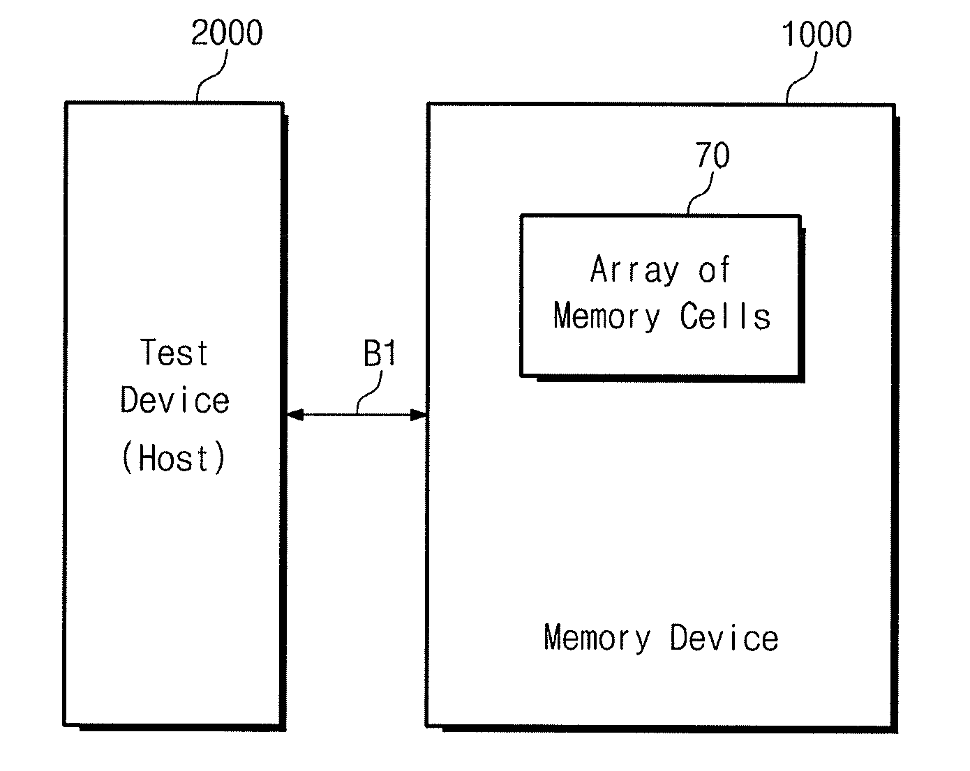
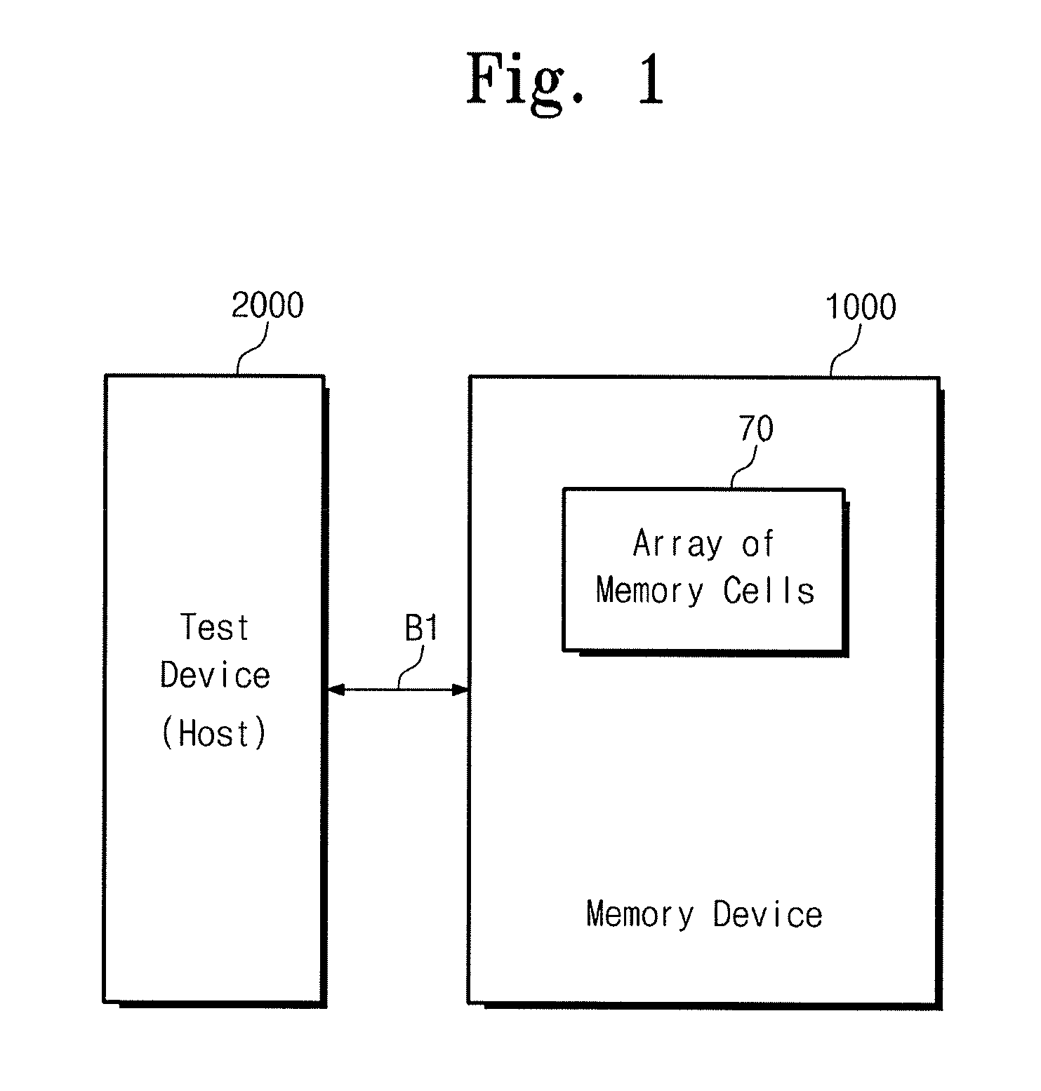
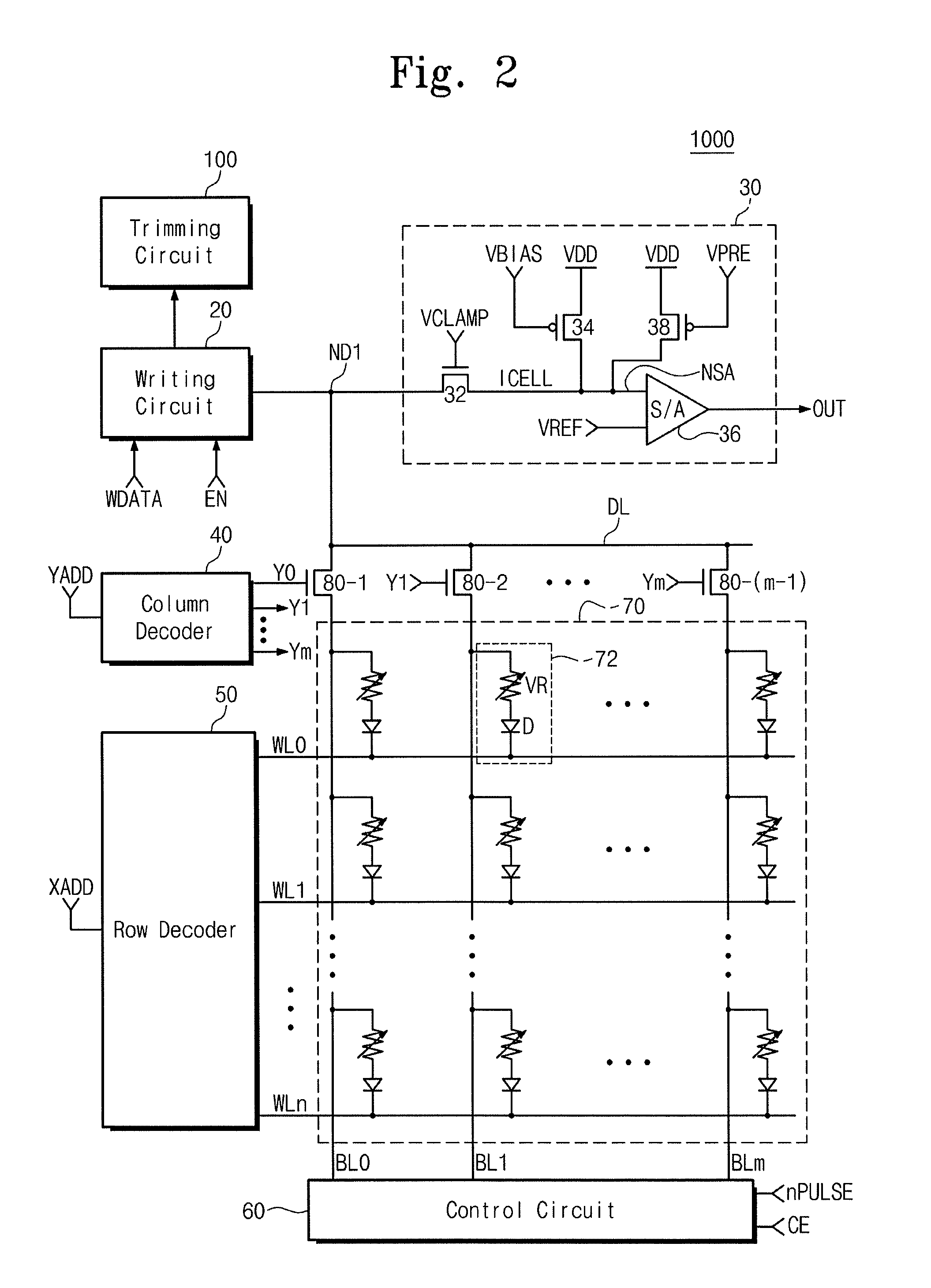
The patent describes a resistance change memory device and a method of programming it. The device includes an array of resistance change memory cells, and a writing circuit for resetting a selected memory cell to a high resistance state by supplying a reset current to the cell. The level of the reset current depends on the distribution of initial reset currents for the array. The device can be trimmed to adjust the program current level, and a wafer burn-in operation can be performed. The method includes measuring the distribution of initial reset currents, determining a representative reset current value, and calculating the level of the program current by adding or subtracting the representative reset current value from a firing ratio. The device can be programmed by applying a pulse of electrical current to change the state of the memory cell, and the second state can be the RESET state or the SET state. The method may also include opening one or more fuses in the memory device after fabrication of the wafer to fix the program.

Problems solved by technology

In a volatile semiconductor memory device such as a random access memory (RAM), data may be stored and read while power supplies are provided, and data may be lost when the power supplies are interrupted.

Method used


Image

  • Resistance change memory device and current trimming method thereof
  • Resistance change memory device and current trimming method thereof
  • Resistance change memory device and current trimming method thereof

Examples


Embodiment Construction

[0038]Example embodiments will now be described more fully hereinafter with reference to the accompanying drawings; however, they may be embodied in different forms and should not be construed as limited to the embodiments set forth herein. Rather, these embodiments are provided so that this disclosure will be thorough and complete, and will fully convey the scope of the invention to those skilled in the art.

[0039]In the drawing figures, the dimensions of layers and regions may be exaggerated for clarity of illustration. It will also be understood that when a layer or element is referred to as being “on” another layer or substrate, it can be directly on the other layer or substrate, or intervening layers may also be present. Further, it will be understood that when a layer is referred to as being “under” another layer, it can be directly under, and one or more intervening layers may also be present. In addition, it will also be understood that when a layer is referred to as being “b...


PUM


Abstract

A resistance change memory device includes an array of resistance change memory cells, and a writing circuit configured to reset a selected memory cell to a high resistance state by supplying a RESET current to the selected memory cell in the array of resistance change memory cells in a program operation mode, wherein a level of the RESET current depends on a distribution of initial RESET currents for the array of resistance change memory cells.

Description

CROSS-REFERENCE TO RELATED APPLICATIONS[0001]This U.S. non-provisional patent application claims priority under 35 U.S.C. §119 of Korean Patent Application No. 10-2011-0083412, filed on Aug. 22, 2011, the entire contents of which are hereby incorporated by reference.BACKGROUND[0002]1. Field[0003]Embodiments relate to a resistance change memory device and a current trimming method thereof.[0004]2. Description of the Related Art[0005]Semiconductor memory devices are used to store data, and include volatile semiconductor memory devices and nonvolatile semiconductor memory devices. In a volatile semiconductor memory device, data may be stored by charge and discharge of a capacitor or a latch operation of flip flop. In a volatile semiconductor memory device such as a random access memory (RAM), data may be stored and read while power supplies are provided, and data may be lost when the power supplies are interrupted. The volatile semiconductor memory devices are frequently used as a main...

Claims


Application Information

Patent Timeline
IPC IPC(8): G11C11/00
CPCG11C8/00G11C13/00G11C13/0004G11C13/0007G11C13/0038G11C13/0069G11C2029/5006G11C2013/0076G11C2013/0083G11C2013/0092G11C11/16G11C29/021G11C29/028G11C17/16G11C11/1675
Inventor LEE, JUNG HYUKHA, DAEWONSIM, KYU-RIE
Owner SAMSUNG ELECTRONICS CO LTD
Learn More