Brush holder of slip ring

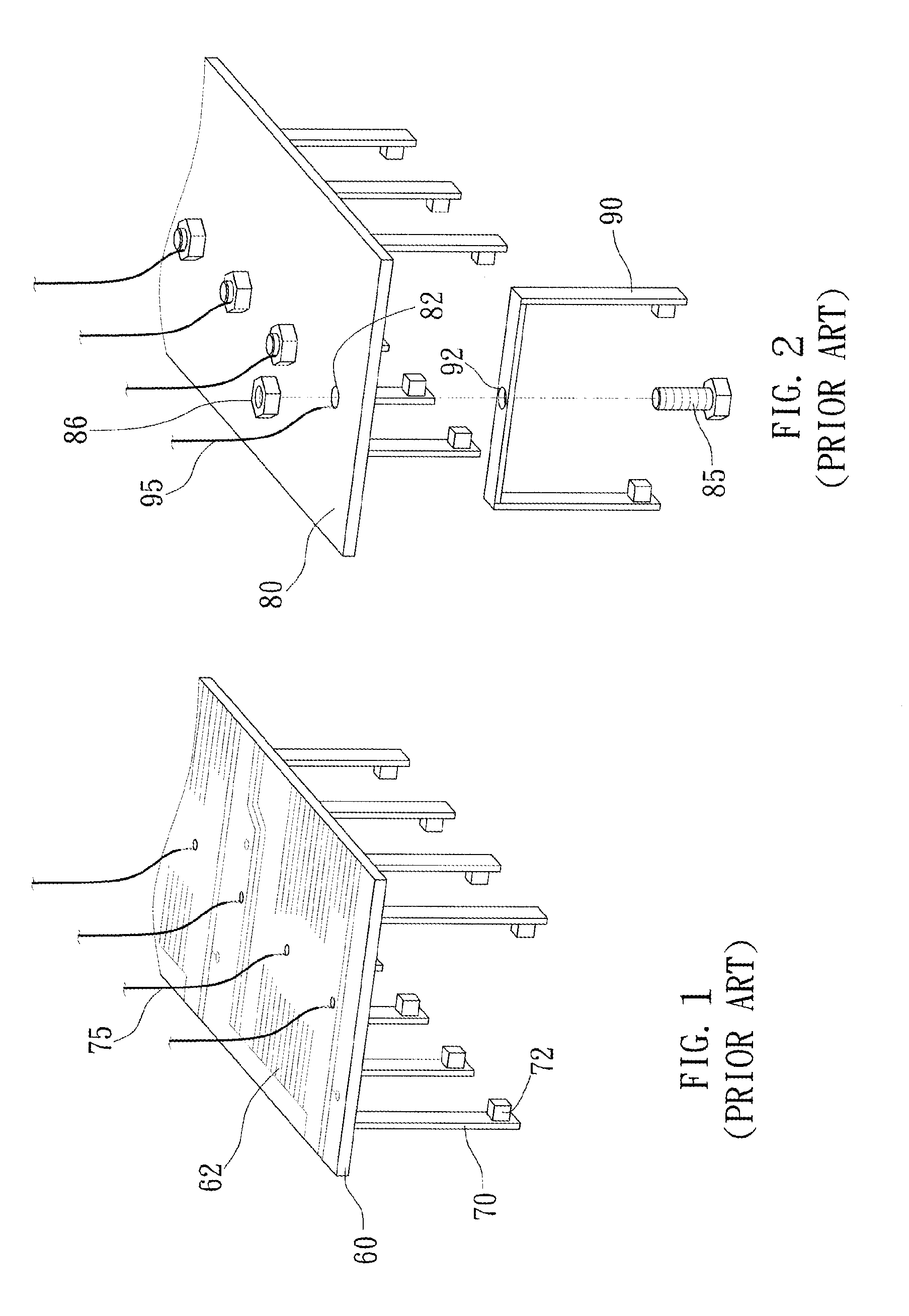
a technology of slip ring and brush holder, which is applied in the field of electromechanical systems, can solve the problems of unstable electrical signal transmission, high cost of design and manufacture of substrate, and complex conductor pattern of substrate b>62/b>, and achieve the effect of stable signal transmission

Active Publication Date: 2013-03-07
TAIWAN LONG HAWN ENTERPRISES
View PDF19 Cites 13 Cited by
  • Summary
  • Abstract
  • Description
  • Claims
  • Application Information

AI Technical Summary

Benefits of technology

[0008]The primary objective of the present invention is to provide a brush holder of a slip ring, which may be assembled in a fast way, and has a low cost and stable electrical signal transmission, and furthermore, it may change its size according to the requirement.
[0011]Therefore, the brush holder may be formed by serially connecting the brush holder units in a fast and easy way, and it provides a stable signal transmission.

Problems solved by technology

However, the conductor pattern 62 of the substrate 60 is very complex that it costs much to design and manufacture the substrate 60.
However, the bolt 85 and the nut 86 will be loose or get rust after a time of use that the electrical signal transmission will become unstable.

Method used


Image

  • Brush holder of slip ring
  • Brush holder of slip ring
  • Brush holder of slip ring

Examples


Embodiment Construction

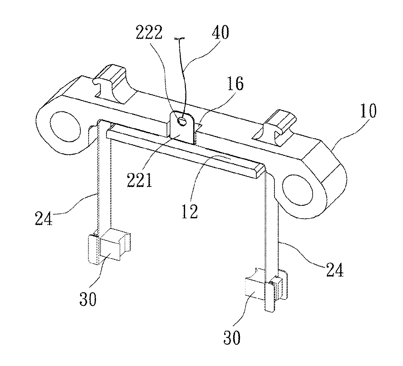
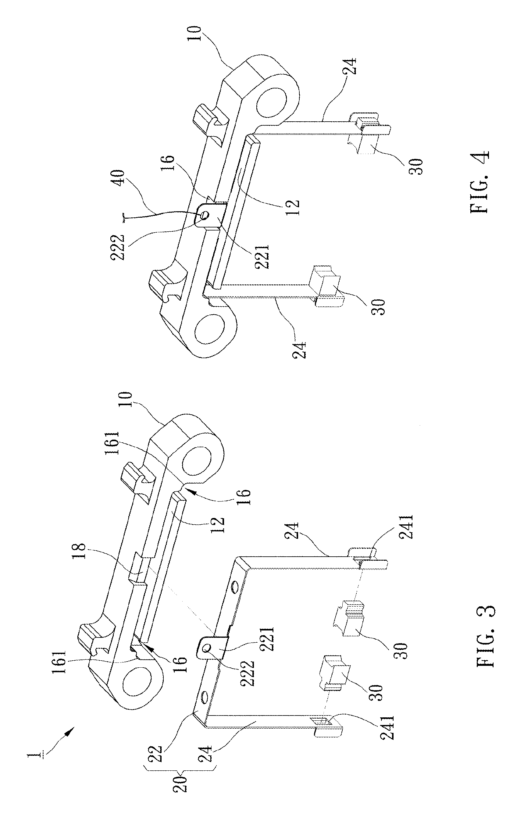
[0023]A brush holder of a slip ring of the preferred embodiment of the present invention is formed by a plurality of brush holder units 1 in serial connection. As shown in FIG. 3 to FIG. 5, each brush holder unit 1 includes an insulating base 10, a brush frame 20, and two carbon brushes 30.

[0024]The insulating base 10 is made of an insulating material. The insulating base 10 has a recess 12 and a protrusion 14 at opposite sides. The insulating base 10 further has two slots 16 which are vertical to the recess 12 and connected to opposite ends of the recess 12.

[0025]The recess 12 is a transverse and elongated slot. The insulating base 10 further has an indentation 18 above the recess 12 and communicated with the recess 12. As shown in FIG. 6, the protrusion 14 is a transverse and elongated block with an inclined face 141 adjacent to a top thereof that a thickness at the top of the protrusion 14 is smaller than a thickness at a bottom. As shown in FIG. 7, each slot 16 has a first end a...


PUM


Abstract

A brush holder of the present invention is formed by a plurality of brush holder units in serial connection. Each brush holder unit includes an insulating base, a brush frame, and two carbon brushes. The insulating base has a protrusion and a recess on opposite sides. The brush frame has a main body received in the recess and two branches projected from opposite ends of the main body. The carbon brushes are provided on the branches of the brush frame. The protrusion of the brush holder unit is inserted into the recess of another brush holder unit to serially connect the brush holder units as well as to secure the brush frame in the recess. Therefore, the brush holder may be formed by serially connecting the brush holder units in a fast and easy way, and it provides a stable signal transmission.

Description

BACKGROUND OF THE INVENTION[0001]1. Field of the Invention[0002]The present invention relates generally to an electro-machine system, and more particularly to a brush holder of a slip ring.[0003]2. Description of the Related Art[0004]When an electro-mechanical system, such as electric machine or power generator, is running, a slip ring serves the function of electrical signal transmission between a running device and a static device to input / output signals and to change the direction. The slip ring has several advantages including raising the system's performance, simplifying the structure, and avoiding the wire from being breaking when the system is running.[0005]Typically, the slip ring is provided with carbon brushes for signal transmission. FIG. 1 shows a conventional brush holder of the slip ring on which the carbon brushes are provided. The brush holder includes a substrate 60 and a plurality of brush frames 70. The substrate 60 has a conductor pattern 62 thereon, and each bru...

Claims


Application Information

Patent Timeline
Patent Type & Authority Applications(United States)
IPC IPC(8): H01R39/41
CPCH01R39/39H01R39/385
Inventor YU, MENG-CHIULIAO, SU-CHEN
Owner TAIWAN LONG HAWN ENTERPRISES
Why Eureka
Try Eureka