Power switching apparatus and method for improving current sense accuracy

a technology of power switching and current sense, applied in the direction of electronic switching, pulse technique, instruments, etc., to achieve the effect of improving current sense accuracy

Active Publication Date: 2013-03-07
NXP USA INC
View PDF8 Cites 27 Cited by
  • Summary
  • Abstract
  • Description
  • Claims
  • Application Information

AI Technical Summary

Benefits of technology

[0008]The present invention provides a power switching apparatus and a method for improving current sense accuracy in a power switching apparatus as described in the accompanying claims.

Problems solved by technology

However, when the switch is actuated, the resistance must pass through a state where a considerable portion of the load's rated power is dropped in the switch, demanding robust switching devices.

Method used


Image

  • Power switching apparatus and method for improving current sense accuracy
  • Power switching apparatus and method for improving current sense accuracy
  • Power switching apparatus and method for improving current sense accuracy

Examples


Embodiment Construction

[0019]Because the illustrated embodiments of the present invention may for the most part, be implemented using electronic components and circuits known to those skilled in the art, details will not be explained in any greater extent than that considered necessary as illustrated, for the understanding and appreciation of the underlying concepts of the present invention and in order not to obfuscate or distract from the teachings of the present invention.

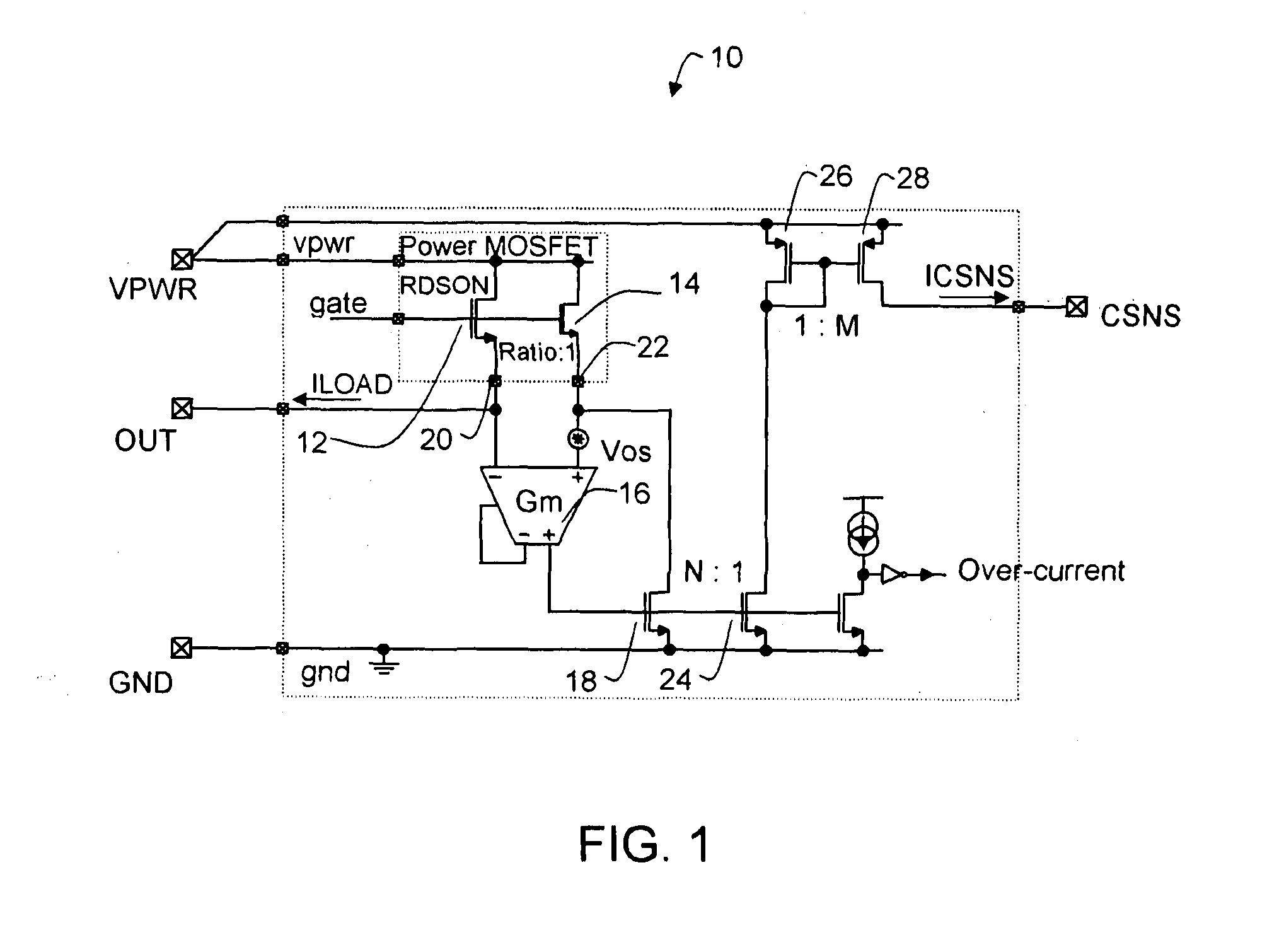
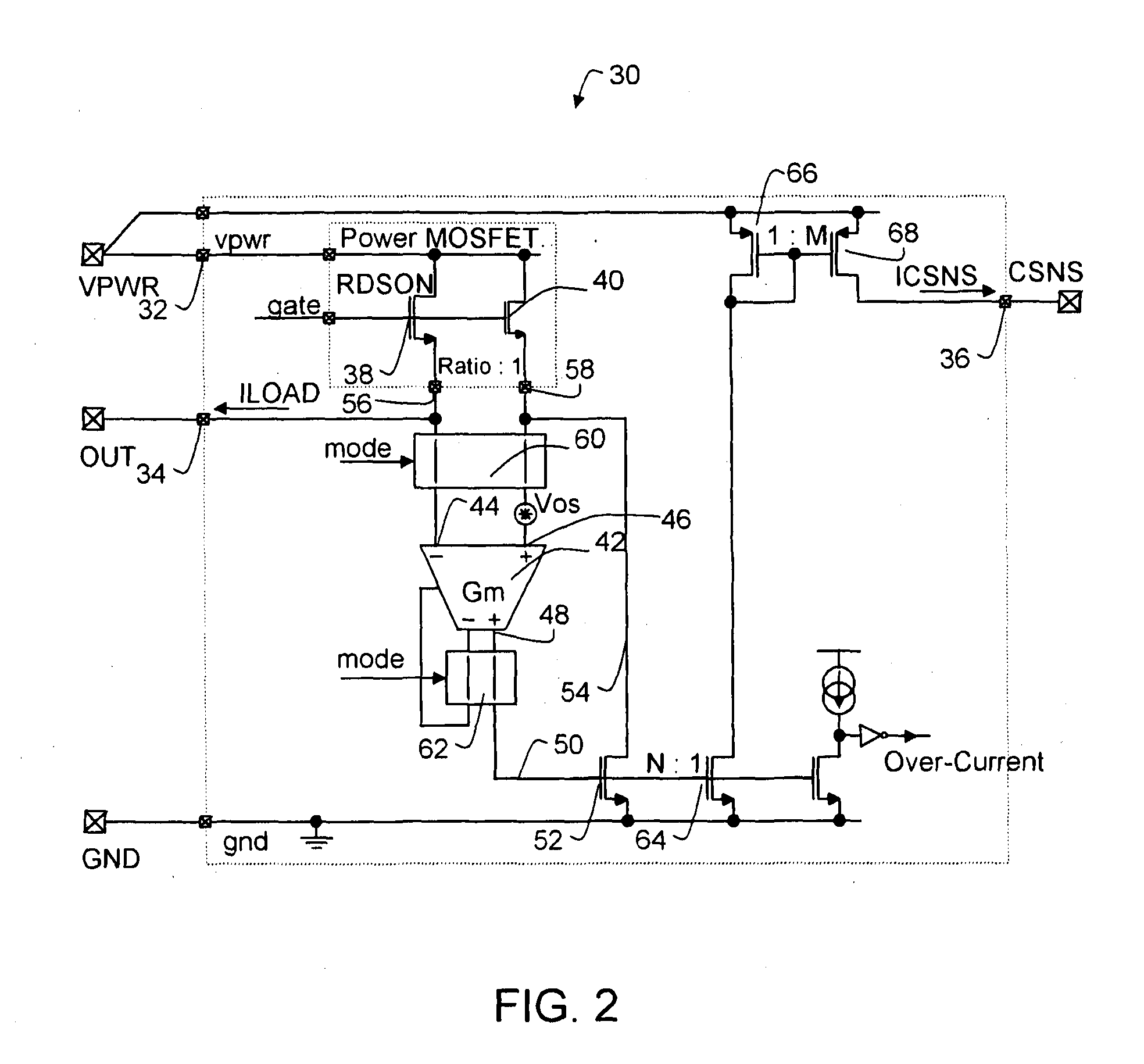
[0020]Referring to FIG. 2, an example of an embodiment of a power switching circuit arrangement 30 of a power switching apparatus in a first mode is shown. A power switching apparatus may comprise a power switching circuit arrangement 30 comprising an input 32 connectable to a power supply (VPWR), a first output 34 connectable to a load and a second output 36 arranged to provide a sense current (ICSNS) depending on a load current (ILOAD) flowing through the load. It may comprise a power switching device 38 and a sense device 40, such ...


PUM


Abstract

A power switching apparatus having a mechanism for improving current sense accuracy is provided. The power switching apparatus includes an output arranged to provide a sense current depending on a load current, a power switching device, a sense device, and a difference amplification device. The difference amplification device includes a first and a second amplifier input, at least one amplifier output connected to a current sense feedback loop arranged to reduce a difference of potentials between the first and the second amplifier input. A terminal of the power switching device and a terminal of the sense device are connected to an input and another terminal of the power switching device and a second terminal of the sense device are coupled to a first cross-coupling switching module.

Description

FIELD OF THE INVENTION [0001]This invention relates to a power switching apparatus and a method for improving current sense accuracy in a power switching apparatus.BACKGROUND OF THE INVENTION[0002]In electronics, a switch is an electrical component that can break an electrical circuit, interrupting the current or diverting it from one conductor to another. When a switch is designed to switch significant power, the transitional state of the switch as well as the ability to stand continuous operating currents must be considered. When a switch is in the on state its resistance is very low and very little power is dropped in the contacts. When a switch is in the off state its resistance is extremely high and even less power is dropped in the contacts. However, when the switch is actuated, the resistance must pass through a state where a considerable portion of the load's rated power is dropped in the switch, demanding robust switching devices. The electrical actuator for a motor, a magn...

Claims


Application Information

Patent Timeline
Patent Type & Authority Applications(United States)
IPC IPC(8): G05F1/10
CPCH03K17/122
Inventor SHUVALOV, DENIS
Owner NXP USA INC
Why Eureka
Try Eureka