
Current detecting circuit for overload protection and overcurrent protection of brushless direct current motor
A technology of current detection circuit and brushed DC motor, which is applied in the direction of measurement using digital measurement technology, can solve the problems of affecting control accuracy, saturation of transformer magnetic core, poor accuracy, etc., and achieve simple circuit structure and current detection accuracy High and low cost effect
- Summary
- Abstract
- Description
- Claims
- Application Information
AI Technical Summary
Problems solved by technology
Method used
Image

Examples
Embodiment Construction
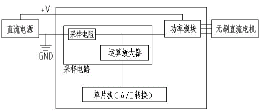
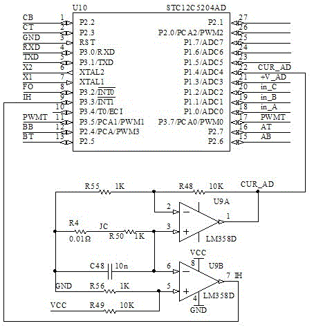
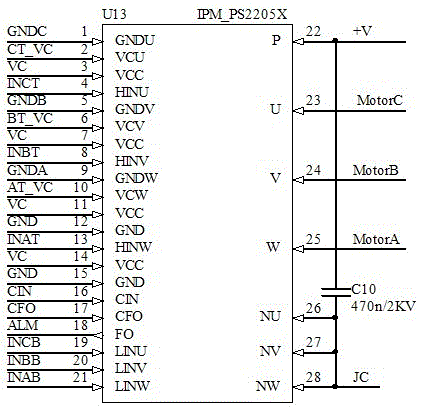
[0011] Such as figure 1 , 2 , 3, the current detection circuit for brushless DC motor overload protection and overcurrent protection, including single-chip microcomputer, current sampling circuit and power module, the current sampling circuit is connected with the single-chip microcomputer and power module respectively; the specific circuit connection is: current sampling In the circuit, pin 1 of the operational amplifier chip U9 is connected to pin 22 of the microcontroller and one end of resistor R48, pin 2 is connected to one end of resistor R55 and the other end of resistor R48, pin 3 is connected to resistor R50 and one end of capacitor C48 , The 6-pin connection of the operational amplifier chip U9, the 5-pin connection with one end of the resistor R56 and the resistor R49, the 7-pin connection with the 9-pin connection of the single-chip microcomputer U10, the 4-pin connection with the public ground GND, and the 8-pin connection with the chip power supply VCC; The 22 p...
PUM
 Abstract
Description
Claims
Application Information