
Frequency conversion apparatus and frequency conversion method

A technology of frequency conversion device and current detection resistor, which is applied in the field of power frequency conversion, can solve the problems of large current sampling error, poor current detection accuracy, and influence on the reconstruction accuracy of each phase of AC power, and achieve the goal of improving current detection accuracy and reconstruction accuracy Effect

Inactive Publication Date: 2015-11-04
BOSCH REXROTH (XIAN) ELECTRIC DRIVES & CONTROLS CO LTD XIAN
View PDF4 Cites 2 Cited by
  • Summary
  • Abstract
  • Description
  • Claims
  • Application Information

AI Technical Summary

Problems solved by technology

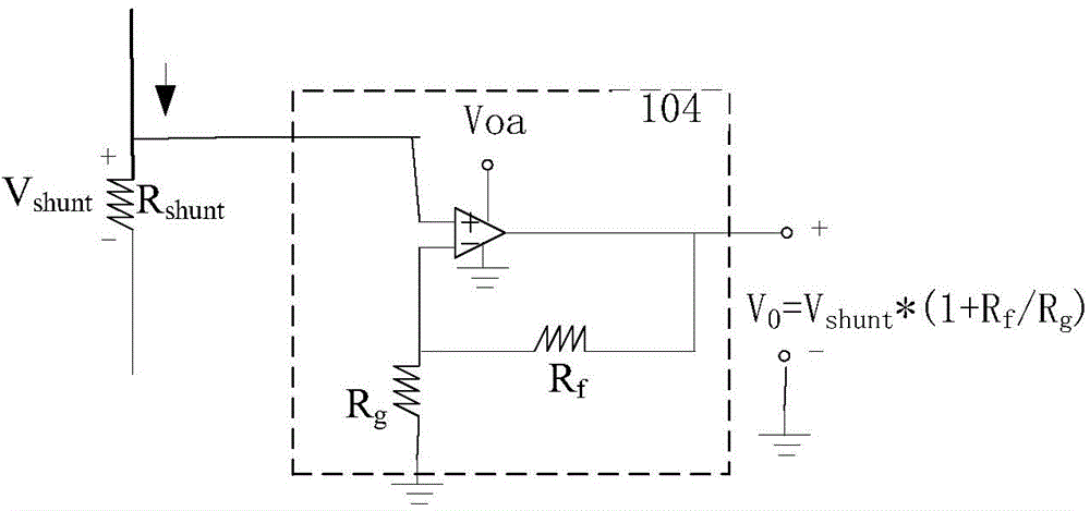
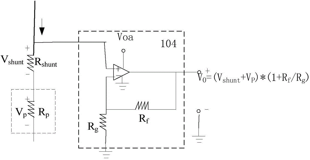
The op amp output voltage becomes V 0 =(V shunt +V g )×(1+Rf / Rg), which makes the current detection of the current detection part inaccurate and affects the reconstruction accuracy of each phase of the AC power
[0005] In addition, when the IGBT109 switches, the reverse recovery current of the antiparallel diode (not shown in the figure) connected in parallel with the IGBT109 and the current detection resistor R shunt The stray parameters on the bus lead to oscillation, which makes the current sampling error near the IGBT switching time point very large
[0006] Therefore, in the frequency conversion device in the prior art where a single resistor samples the DC bus current and reconstructs the motor phase current, due to the parasitic impedance R p , Influenced by the reverse recovery current of the antiparallel diode connected in parallel with the IGBT and the stray parameters on the bus, the current detection accuracy is poor, which affects the reconstruction accuracy of each phase of the AC power

Method used


Image

  • Frequency conversion apparatus and frequency conversion method
  • Frequency conversion apparatus and frequency conversion method
  • Frequency conversion apparatus and frequency conversion method

Examples


Embodiment Construction

[0028] Some preferred embodiments of the present invention are described in more detail below with reference to the accompanying drawings. Although preferred embodiments of the present disclosure are shown in the drawings, it should be understood that the present disclosure may be embodied in various forms and should not be limited to the embodiments set forth herein. Rather, these embodiments are provided so that this disclosure will be thorough and complete, and will fully convey the scope of the disclosure to those skilled in the art.

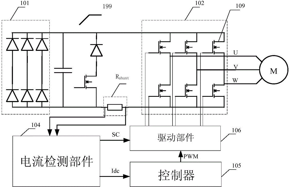
[0029] image 3 A block diagram of a frequency conversion device according to an embodiment of the present invention is shown. The frequency conversion device according to one embodiment of the present invention includes a rectifier 101, an intermediate DC part 199, a current detection resistor R shunt , the current detection part 104, the controller 105, the driving part 106 and the inverter 102. The rectifier 101 converts input AC power...


PUM


Abstract

The invention relates to a frequency conversion apparatus and a frequency conversion method. The frequency conversion apparatus comprises a rectifier used for transforming inputted alternating current (AC) into direct current (DC); an intermediate DC part used for stabilizing the DC transformed by the rectifier, and provided with a current detection resistor; a current detection component used for collecting and amplifying differential signals reflecting the voltage difference between two ends of the current detection resistor so as to detect the current passing through the current detection resistor; a controller used for calculating each reconstructed AC phase current in dependence on the detected current of the current detection resistor; and an inverter used for converting the DC stabilized by the intermediate DC part into AC in dependence on the calculated reconstructed AC phase currents. The scheme can improve the current detection precision in the frequency conversion apparatus, so as to increase AC phase reconstruction precision and improve frequency converter control performance.

Description

technical field [0001] The invention relates to the field of power frequency conversion, in particular to a frequency conversion device and a frequency conversion method. Background technique [0002] In large-scale mechanical equipment driven by motors (such as pump trucks, etc.), when the motor runs beyond the power drive requirements, the excess torque will increase the consumption of active power and cause a waste of electric energy. Therefore, frequency conversion devices are often used to reduce the current output by the motor when the motor is running beyond the power drive requirements. The frequency conversion device includes a rectifier, an inverter and an intermediate DC part. The rectifier rectifies the AC voltage from the grid into DC power and supplies it to the intermediate DC unit. The intermediate DC section includes positive and negative busbars and capacitor banks for stabilizing the DC output from the rectifier so as to provide it to the inverter. The ...

Claims


Application Information

Patent Timeline
Patent Type & Authority Applications(China)
IPC IPC(8): H02M5/458
Inventor 罗斌马鑫
Owner BOSCH REXROTH (XIAN) ELECTRIC DRIVES & CONTROLS CO LTD XIAN
Learn More