Reducing phase locked loop phase lock time

a phase lock and phase lock technology, applied in the field of phase lock loops, can solve the problems of excessive ringing of the phase lock loop in its transient settling behavior, and achieve the effect of reducing the lock tim

Active Publication Date: 2013-03-07
GLOBALFOUNDRIES US INC
View PDF15 Cites 24 Cited by
  • Summary
  • Abstract
  • Description
  • Claims
  • Application Information

AI Technical Summary

Benefits of technology

[0015]According to an aspect of the present principles, there is provided a method for reducing lock time in a phase locked loop. The method includes detecting a saturation condition on a path within the phase locked loop. The method further includes temporarily applying saturation compensation along the path when the saturation condition is detected.
[0016]According to another aspect of the present principles, there is provided an apparatus for reducing lock time in a phase locked loop. The apparatus includes a saturation compensator for detecting a saturation condition on a path within the phase locked loop, and temporarily applying saturation compensation along the path when the saturation condition is detected.
[0018]According to still another aspect of the present principles, there is provided a method for reducing lock time in a phase locked loop having an integral control path and a proportional control path. The method includes detecting a saturation condition on the proportional control path. The method further includes temporarily applying saturation compensation along the proportional control path when the saturation condition is detected by adjusting a relative gain on the proportional control path. The proportional control path includes a coarse band controller for controlling an oscillator coarse band. The relative gain on the path is adjusted by modulating the oscillator coarse band between an incremented state and an original state to provide at least one of a reduced average frequency change and a reduced average phase change over a given time period as compared to using only the incremented state. The original state corresponds to a non-saturation condition of the proportional control path.

Problems solved by technology

However if ζ<1, then the PLL can exhibit excessive ringing in its transient settling behavior.

Method used


Image

  • Reducing phase locked loop phase lock time
  • Reducing phase locked loop phase lock time
  • Reducing phase locked loop phase lock time

Examples


Embodiment Construction

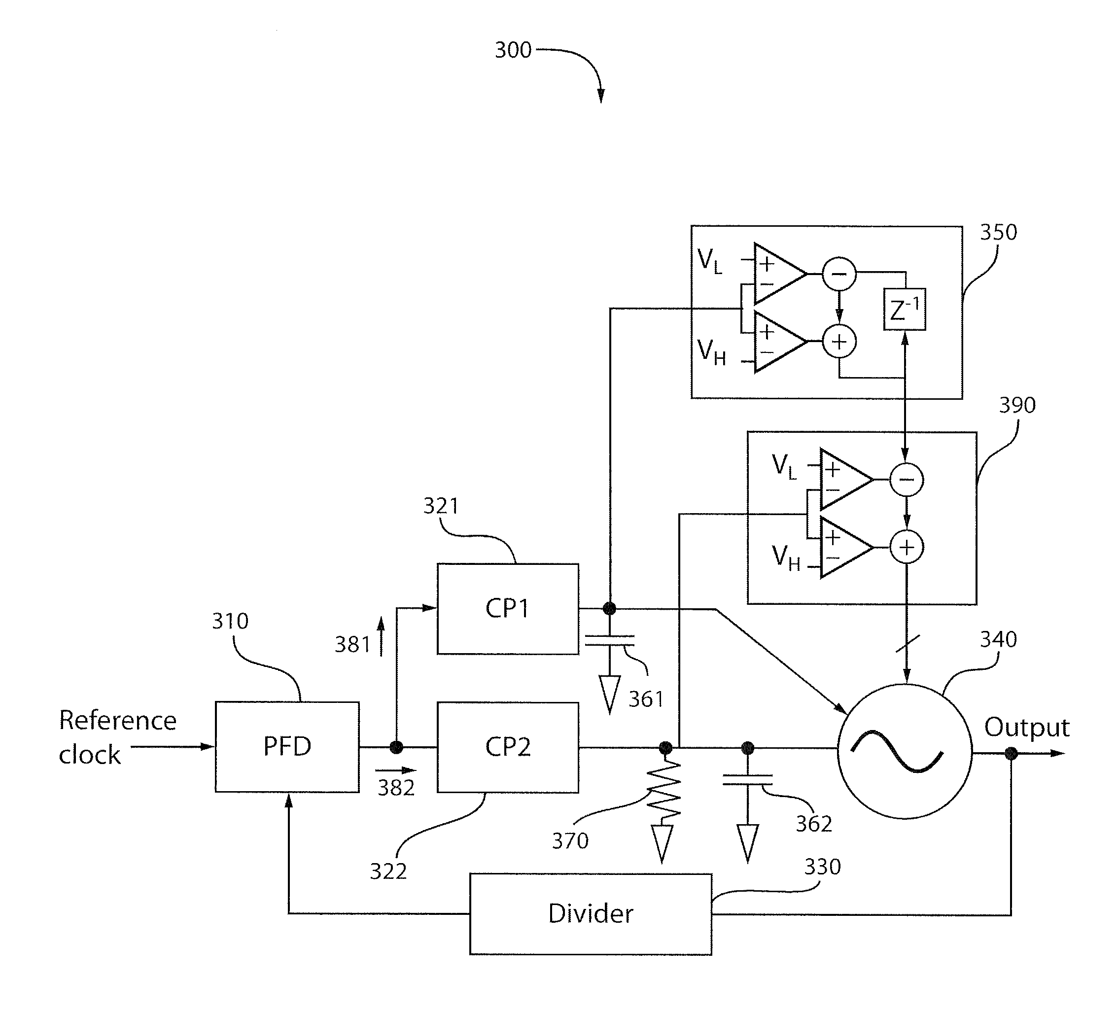
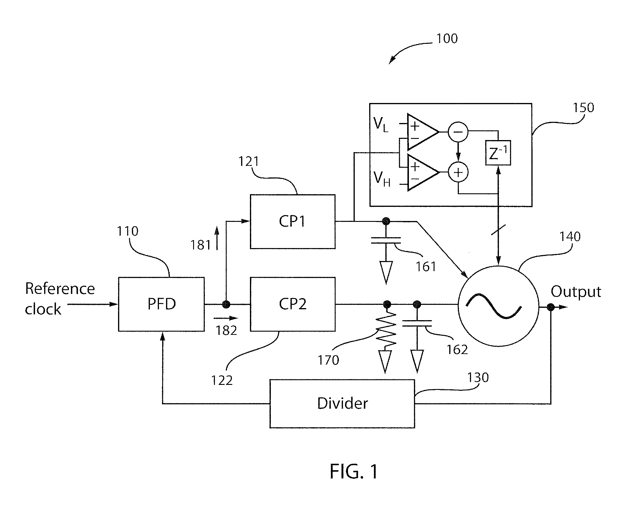
[0028]The present principles are directed to reducing phase locked loop (PLL) phase lock time (frequency acquisition time). Advantageously, the present principles are suitable for any PLL architecture in which the proportional path can saturate in the presence of large phase deviations. Examples of suitable PLLs to which the present principles may be applied include, but are not limited to, dual-path analog or digital PLLs.

[0029]In an embodiment of the present principles, the frequency acquisition time of a dual path PLL is reduced by temporarily incrementing / decrementing the coarse bands of the voltage controlled oscillator (VCO) when the proportional voltage goes above / below its unsaturated range. This is the equivalent of extending the proportional path range. A major advantage of this approach is that it requires very little additional circuitry. The VCO's coarse band control circuit already controls the VCO bands. Hence, such additional circuitry pertains to detecting when the ...


PUM


Abstract

There is provided a method for reducing lock time in a phase locked loop. The method includes detecting a saturation condition on a path within the phase locked loop. The method further includes temporarily applying saturation compensation along the path when the saturation condition is detected.

Description

GOVERNMENT RIGHTS[0001]This invention was made with Government support under Contract No.: FA8650-09-C-7924 (Defense Advanced Research Projects Agency (DARPA)). The Government has certain rights in this invention.BACKGROUND[0002]1. Technical Field[0003]The present invention relates generally to phase locked loops and, in particular, to reducing phase locked loop (PLL) phase lock time.[0004]2. Description of the Related Art[0005]A phase locked loop (PLL) is a control system that aims to generate an output signal having a phase that is related to the phase of an input (i.e., reference) signal. The lock time of a PLL, also known as phase lock time or frequency acquisition time or settling time, is the time that is takes for the phase of the output of the PLL to be locked to (in synchronization with) the phase of the input of the PLL. Of course, it is advantageous that the lock time of a PLL be as small as possible.[0006]FIG. 1 shows a dual path analog phase locked loop (PLL) 100, in ac...

Claims


Application Information

Patent Timeline
Patent Type & Authority Applications(United States)
IPC IPC(8): H03L7/08
CPCH03L2207/06H03L7/0893
Inventor FERRISS, MARKRYLYAKOV, ALEXANDER V.TIERNO, JOSE A.
Owner GLOBALFOUNDRIES US INC
Why Eureka
Try Eureka