
Illumination device

a technology of light emission layer and insulating layer, which is applied in the direction of light emission support device, organic semiconductor device, lighting and heating apparatus, etc., can solve the problems of undesirable user perception of uneven light emission, increase in the thickness of the organic light emission layer during the manufacturing process, and increase in so as to achieve efficient suppression of uneven light emission and further suppress uneven light emission. , the effect of reducing the thickness of the organic light emission layer

Active Publication Date: 2013-03-07
MERCK PATENT GMBH
View PDF20 Cites 0 Cited by
  • Summary
  • Abstract
  • Description
  • Claims
  • Application Information

AI Technical Summary

Benefits of technology

The patent describes an illumination device that reduces uneven light emission, which can be uncomfortable for users. This device achieves this by creating a spatially periodic luminance variation with a constant amplitude, which helps to mask the unevenness of light. The device can be effective and easy to use, with various levels of suppression available depending on user preferences.

Problems solved by technology

As the area of the organic EL device increases, the likelihood of causing non-uniformity in the thickness of the organic light emission layer during a manufacturing process, or the like, increases.
As a result, when the organic EL device emits light, non-uniform luminance, or the like, is exhibited, which may undesirably make a user perceive unevenness in the light emission (also referred to as uneven light emission).
Such uneven light emission may also occur due to degradation of the organic light emission layer, or the like, that is caused in accordance with conditions under which the organic EL device is used.
However, if the user perceives a certain level of uneven light emission due to the variation in the luminance, the quality level of the organic EL device as an illumination device is impaired.

Method used


Image

  • Illumination device
  • Illumination device
  • Illumination device

Examples


Embodiment Construction

[0042]Hereinafter, an embodiment of the present invention will be described with reference to the drawings. In the drawings, parts having identical or similar configurations and functions are denoted by the same reference numeral, and redundant descriptions are omitted below. It is to be noted that the drawings are merely schematic, and the sizes, shapes, positional relationships, and the like, of structures are not precisely illustrated in the drawings.

[0043]

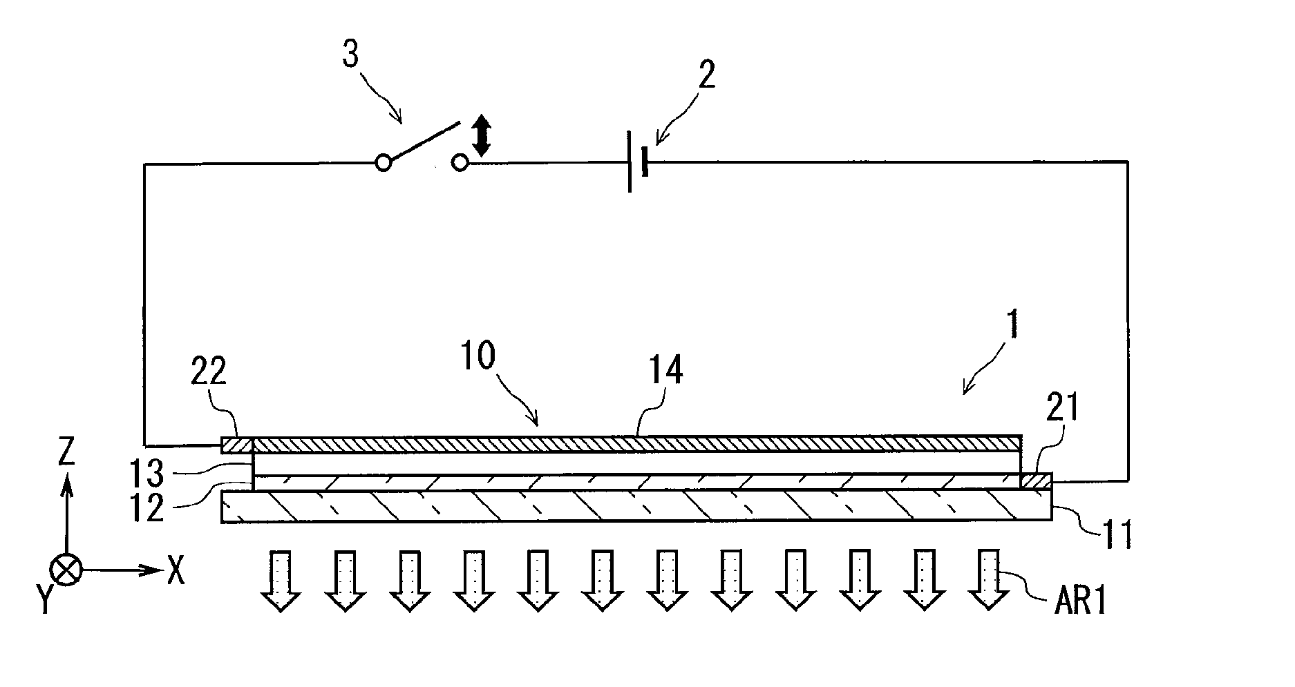
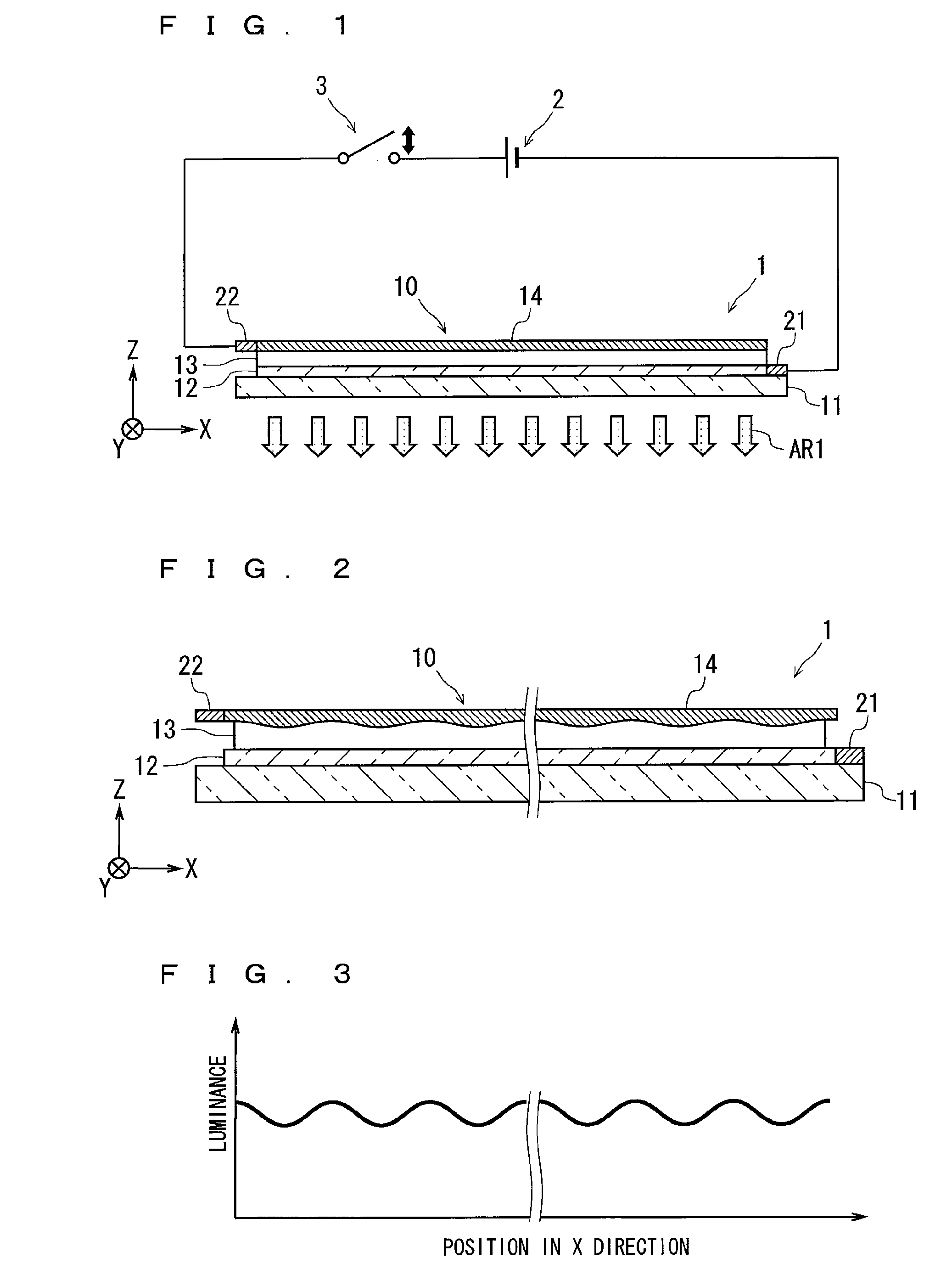
[0044]FIG. 1 is a diagram schematically showing an outline configuration of an illumination device 1 according to an embodiment. FIG. 1 additionally shows a left-handed XYZ coordinate system whose XY plane defines a plane extending in parallel with a part (also referred to as a light-emitting surface) of the illumination device 1 that causes light emission in the shape of a surface. In FIG. 2 and subsequent Figures, for the purpose of clarifying a directional relationship, one or more axes corresponding to any of the three XYZ ...


PUM


Abstract

An object is to provide an illumination device in which uneven light emission that a user may perceive is suppressed. To achieve the object, an illumination device is adopted that includes a power feeding portion and a surface light emitter including a light-emitting surface configured to emit light in accordance with a voltage applied by the power feeding portion and to cause light emission in the shape of a surface. The surface light emitter generates a spatially periodic luminance variation having a substantially constant amplitude.

Description

TECHNICAL FIELD[0001]The present invention relates to an illumination device that performs surface light emission.BACKGROUND ART[0002]In recent years, as a device (also called a surface light emission device) for performing surface light emission which causes reduced power consumption, a light-emitting device (also called an organic EL device) that utilizes an organic EL (organic electroluminescence) is attracting attention, and its application to an illumination device, or the like, is in progress.[0003]The organic EL device includes a structure in which an organic light emission layer is interposed between two electrodes (an anode electrode and a cathode electrode). As the area of the organic EL device increases, the likelihood of causing non-uniformity in the thickness of the organic light emission layer during a manufacturing process, or the like, increases. As a result, when the organic EL device emits light, non-uniform luminance, or the like, is exhibited, which may undesirab...

Claims


Application Information

Patent Timeline
Patent Type & Authority Applications(United States)
IPC IPC(8): F21V21/002H05B44/00
CPCH05B33/08H01L2251/5361H05B44/00
Inventor YAMAMOTO, TOSHITSUGU
Owner MERCK PATENT GMBH
Learn More