Versatile beam and wash optical system for an automated luminaire

an optical system and luminaire technology, applied in the field of automatic luminaires, can solve the problems of large and unwieldy luminaires, difficult automation of pan and tilt movement, and problems with the center of gravity of luminaires

Active Publication Date: 2013-03-07
ROBE LIGHTING
View PDF1 Cites 17 Cited by
  • Summary
  • Abstract
  • Description
  • Claims
  • Application Information

AI Technical Summary

Problems solved by technology

It is problematic to use a large separation with a large lens as such an arrangement makes the luminaire large and unwieldy and makes automation of the pan and tilt movement difficult.
A short focal length lens if constructed as a conventional glass plano-convex lens needs to be very thick and heavy which may also cause problems with the center of gravity of the luminaire, especially if the lens is moved along the optical axis by motors to provide an automated focus function.
As the heavy lens moves the center of gravity of the luminaire is constantly changing and causes problems for the automated pan and tilt systems which are optimized for a balanced mechanical load.
Firstly they may maintain the heavy front lens static and instead move the gobo, iris and shutter assemblies backwards and forwards instead.
Fresnel lenses are well known in the art and can provide a good match to the focal length of an equivalent plano-convex lens, however the image...

Method used


Image

  • Versatile beam and wash optical system for an automated luminaire
  • Versatile beam and wash optical system for an automated luminaire
  • Versatile beam and wash optical system for an automated luminaire

Examples


Embodiment Construction

[0027]Preferred embodiments of the present invention are illustrated in the FIGUREs, like numerals being used to refer to like and corresponding parts of the various drawings.

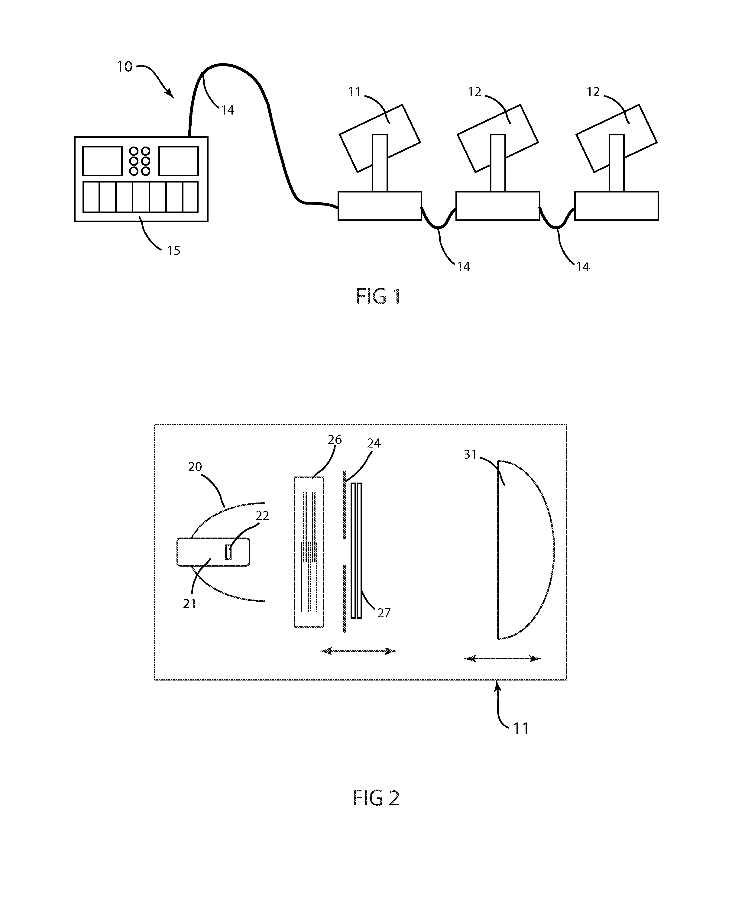
[0028]The present invention generally relates to an automated luminaire, specifically to the configuration of the optical systems within such a luminaire to provide the user selectable option of either a narrow beam output with sharply focused images or a wash light distribution with a large effective source and true blending output distribution.

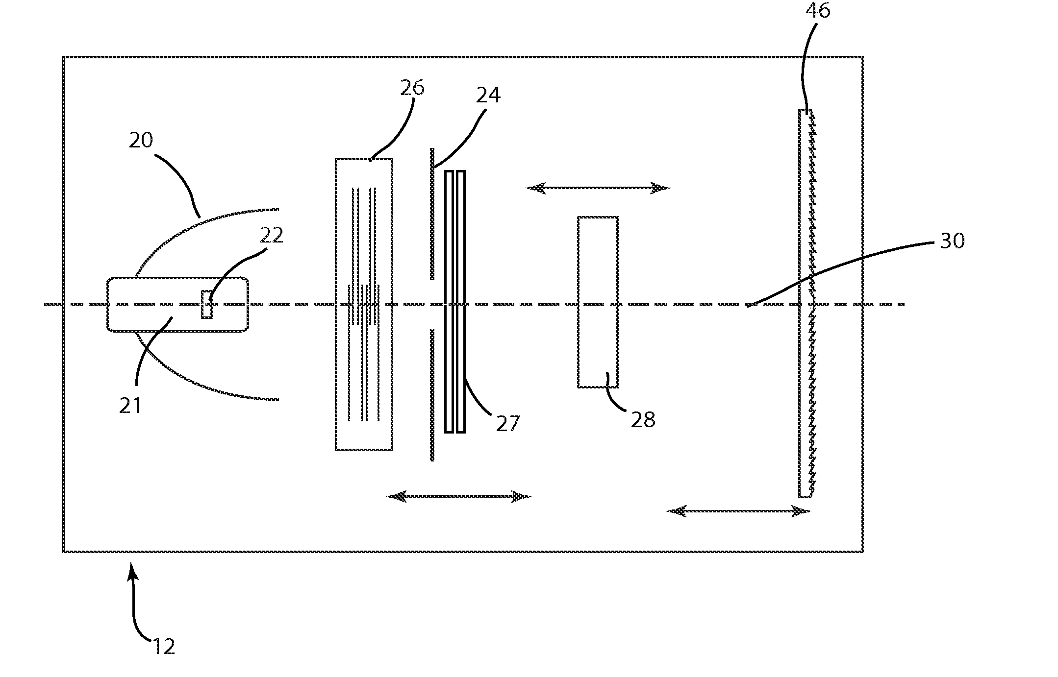
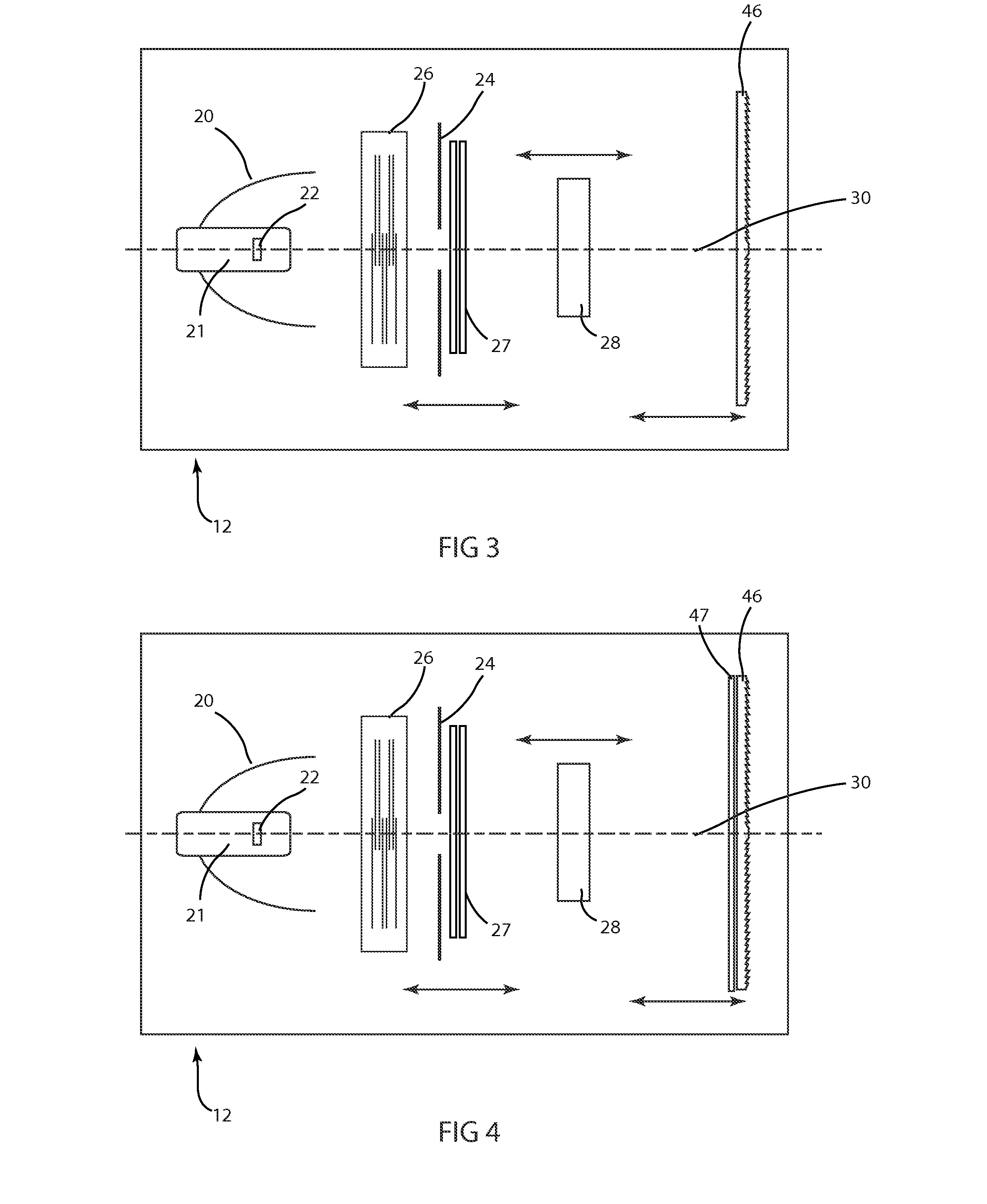
[0029]FIG. 3 illustrates an embodiment of an improved Fresnel output lens luminaire when in beam light mode. Automated luminaire 12 may contain a lamp 21 and reflector 20 where the lamp and reflector may be moved relative to each other for beam hot-spot control, color control components 26 which may include, but are not limited to, color mixing flags or wheels, color wheels and other dichroic color control components, an aperture 24, imaging optical components 27 which ...


PUM


Abstract

Described are an improved automated luminaire 12 and luminaire systems 10 employing an improved output Fresnel lens 46 with an optically planar surface 34 combined with an articulable stippling plate 47. The stippling plate 47 may be inserted and removed immediately behind and adjacent to the planar rear surface of the lens 46 in order to transform the optical system from beam optics to wash optics or immediately adjacent to another articulable lens system 29 directly the light beam toward the previously described Fresnel lens. Further embodiment may include an articulable beam spreader.

Description

RELATED APPLICATIONS[0001]This application is a full utility patent application claiming priority of provisional patent application(s) 61 / 531,062 filed 5 Sep. 2011 and 61 / 599,420 filed 15 Feb. 2012.TECHNICAL FIELD OF THE INVENTION[0002]The present invention generally relates to automated luminaires, specifically to optical systems for use within automated luminaires.BACKGROUND OF THE INVENTION[0003]Luminaires with automated and remotely controllable functionality are well known in the entertainment and architectural lighting markets. Such products are commonly used in theatres, television studios, concerts, theme parks, night clubs and other venues. A typical product will commonly provide control over the pan and tilt functions of the luminaire allowing the operator to control the direction the luminaire is pointing and thus the position of the light beam on the stage or in the studio. Typically this position control is done via control of the luminaire's position in two orthogonal ...

Claims


Application Information

Patent Timeline
IPC IPC(8): F21V17/02F21V5/04
CPCF21S10/007F21V11/14F21V5/045F21W2131/406F21V11/183F21V14/06
Inventor JURIK, PAVELVALCHAR, JOSEPH
Owner ROBE LIGHTING
Why Eureka
Try Eureka