Rotating Drive Shaft Coupling

a technology of rotating drive shaft and coupling, which is applied in the direction of couplings, instruments, manufacturing tools, etc., can solve the problems of less printing accuracy, greater failure probability, and increased shear, so as to reduce manufacturing and maintenance costs, reduce stress transfer from the torque generated between the driving mechanism and the driving mechanism, and achieve more powerful torque

Active Publication Date: 2013-03-07
RAINBOW TECH INT LTD
View PDF4 Cites 59 Cited by
  • Summary
  • Abstract
  • Description
  • Claims
  • Application Information

AI Technical Summary

Benefits of technology

[0007]The present invention is a substantial improvement to the mechanical coupling, because manufacture and maintenance costs can be reduced without sacrificing printing accuracy. Because the twisted coupling hole or recess is engaged with a plurality of helical involute teeth, the stress transferred from the torque generated between the driving mechanism and the driven mechanism is reduced while the coaxial alignment of the driving and driven portions of the coupling is maintained. As a result, more powerful torque may be transferred with the same size coupling or, alternatively, materials of less strength (and less cost) may be used in fabricating the coupling.
[0008]The invention includes a plurality of helical involute teeth projecting from a cylinder, as shown in FIG. 1. The teeth engage with a twisted, preferably petaline recess or coupling hole in the drive shaft, as shown in FIGS. 2 and 3. The invention permits the involute teeth and petaline recess to engage each other so that a curved surface of the gear and a curved surface of the recess engage in three locations. Moreover, this engagement minimizes the shear stress, maximizes the compression force, and distributes the compression force over a greater surface area on the tooth and on the side of the recess. Greater shear means more wear, less printing accuracy, and a greater chance of failure. In testing, these ends of the developer cylinder have outlasted the prior art coupling ends. This endurance, which results from emphasizing the compression force over the shear and spreading it out over a larger area, ultimately means less part wear, less maintenance cost, and greater printing accuracy.

Problems solved by technology

Greater shear means more wear, less printing accuracy, and a greater chance of failure.

Method used


Image

  • Rotating Drive Shaft Coupling
  • Rotating Drive Shaft Coupling
  • Rotating Drive Shaft Coupling

Examples


Embodiment Construction

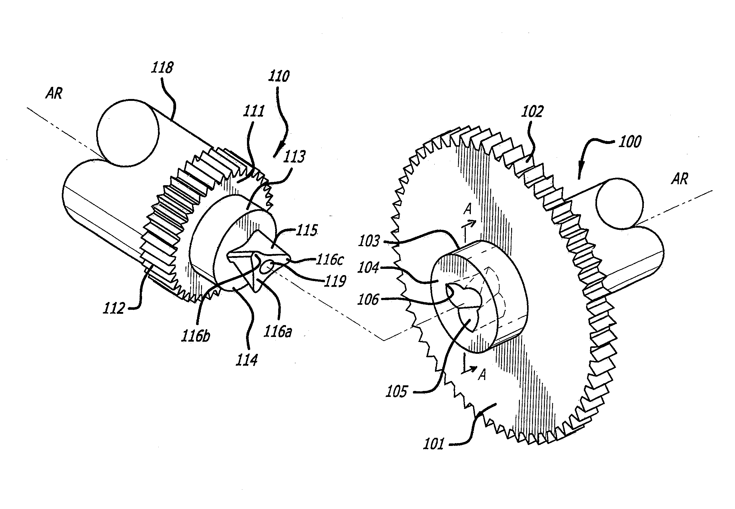
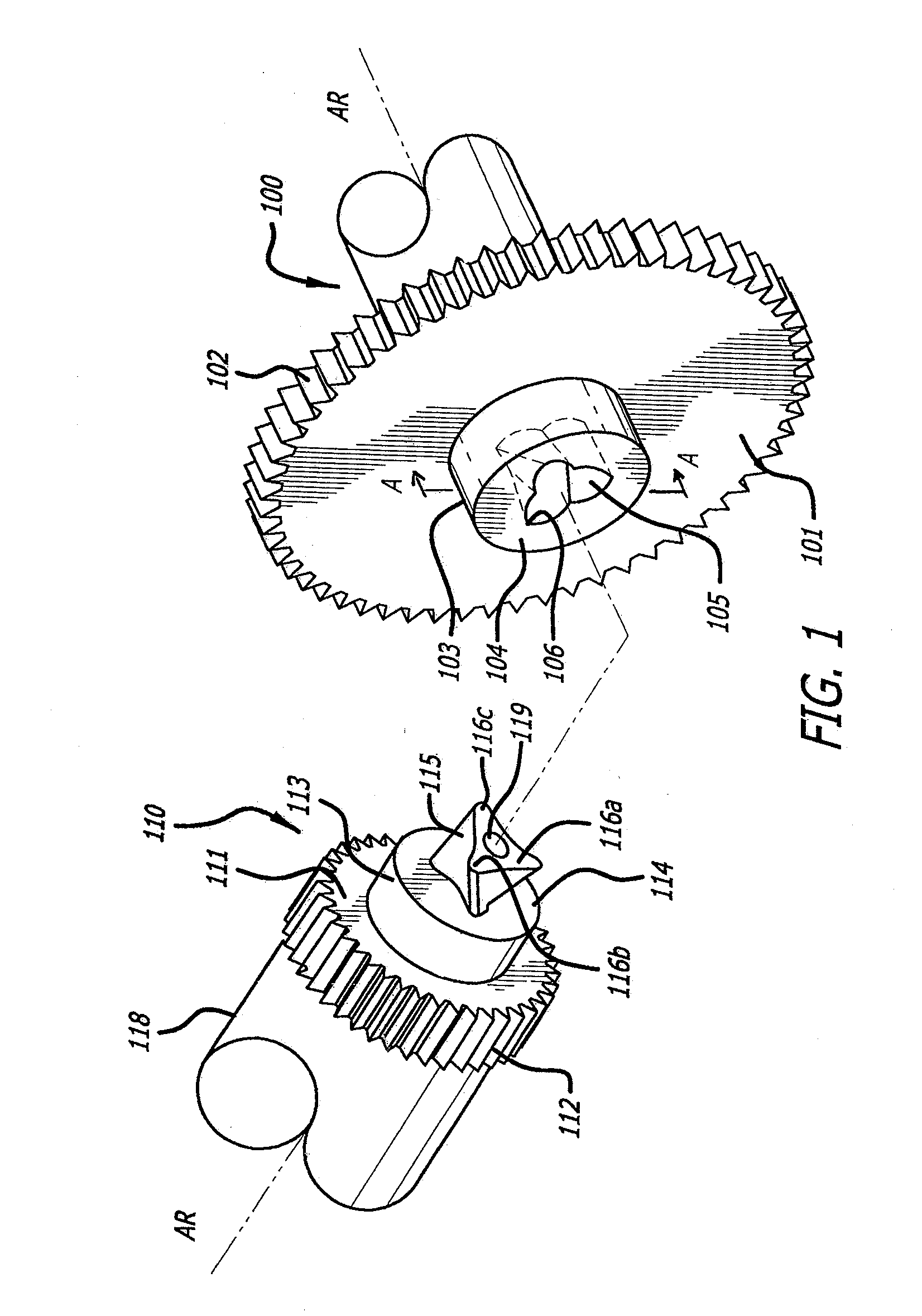
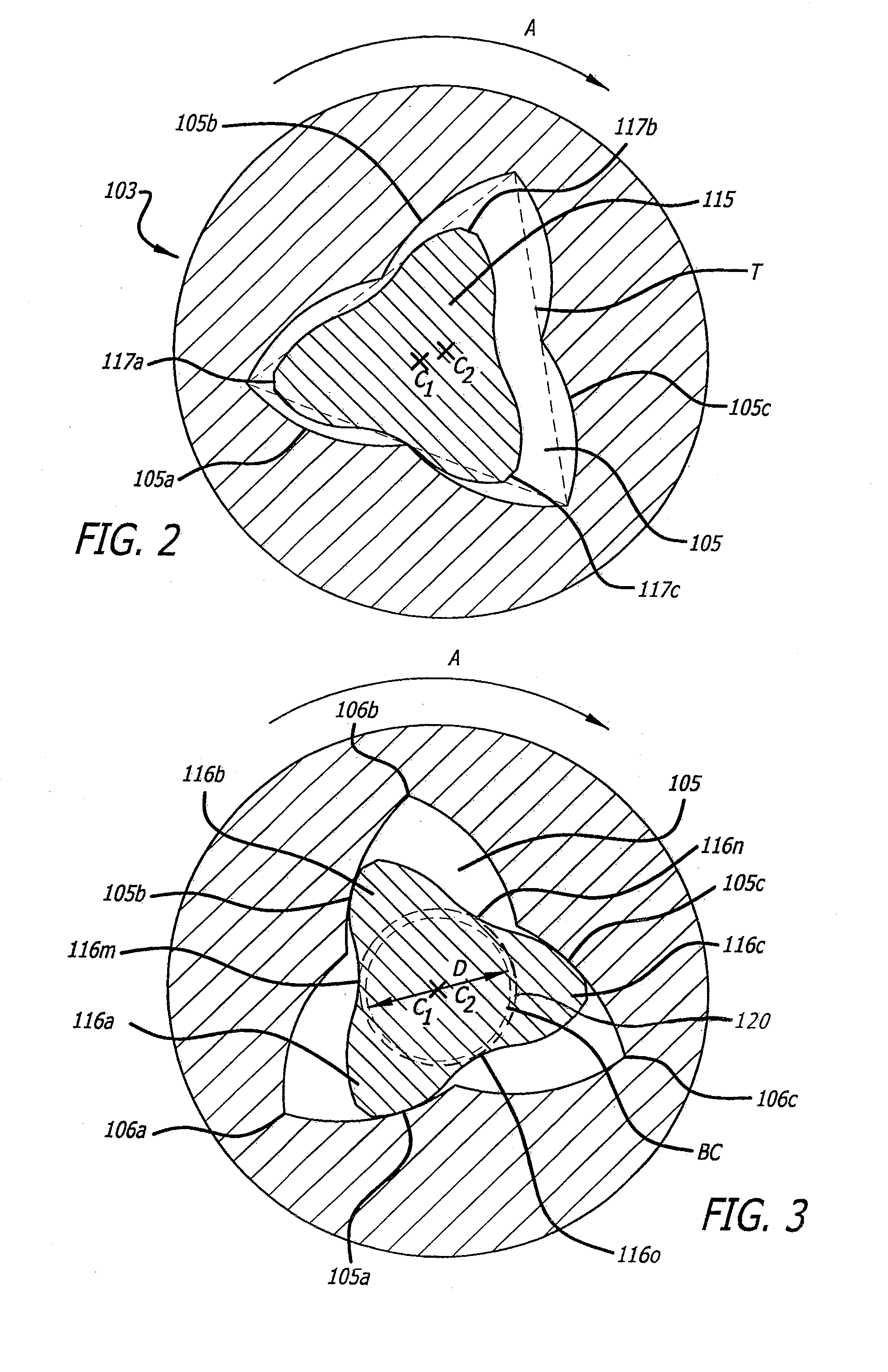
[0019]FIGS. 1-3 depict a preferred embodiment of the present invention. Mounted on the end of developer cylinder 118 is a driven member or driven coupling 110 that is adapted to engage with driving member or driving coupling 100. Drive gear 101 includes a gear shaft 103 at its center and an outside edge 102 having gear teeth. Gear shaft 103 has a front surface 104, which includes a twisted petaline recess 105 having defined vertices 106a, 106b, 106c formed therein. The twisted petaline recess 105 is engageable with the plurality of helical involute teeth 116a, 116b, 116c.

[0020]Driven coupling 110 is attached to photosensitive drum 118 of a replaceable or changeable developer cylinder and has geared driven shaft cylinder 112 that includes shaft cylinder flange 111. Concentric shaft 113 extends longitudinally outwardly from shaft cylinder flange 111. Concentric shaft 113 includes a front surface 114 from which extends an engagement projection 115 that has a plurality of helical invol...


PUM


Abstract

A rotatable coupling is used with a replaceable developer cartridge and electrostatographic image devices. The coupling has a driven portion and a driving portion. The driven portion has a shaft with a connecting portion that has a plurality of helical involute teeth extending outwardly. The driving portion has an end with a gear shaft and a twisted petaline recess in the gear shaft. The sides of the recess are engageable with the helical involute teeth so that the driving portion drives the driven portion and transmit torque.

Description

FIELD OF THE INVENTION[0001]This invention relates to the field of mechanically transmitting rotational force from a drive mechanism that is coupled to another rotational device. The invention can be used in general situations when a drive shaft is coupled to a driven apparatus. The preferred embodiment of the invention is used in the field of electrostatographic image forming devices such as copiers, facsimile machines, electrophotography printers, and replaceable or changeable cartridges for these devices, such as a toner cartridge for a laser printer.BACKGROUND OF THE INVENTION[0002]Many electrophotographic machines, such as photocopiers or laser printers, use a detachable developer cylinder that contains a photosensitive member. The cylinder is also known as a cartridge or developer cartridge, and it is detachably mounted to the complete copier or printer. This construction enables users to maintain the printing capability of the device without the aid of a serviceman.[0003]The ...

Claims


Application Information

Patent Timeline
Patent Type & Authority Applications(United States)
IPC IPC(8): F16D1/02
CPCF16D2001/102F16D1/02F16D1/101Y10T403/7098Y10T403/7005G03G21/186G03G2221/1657
Inventor FAN, ROY
Owner RAINBOW TECH INT LTD
Why Eureka
Try Eureka