
Topology mapping in a distributed processing system

a distributed processing system and topology mapping technology, applied in the field of data processing, can solve the problems of extremely complicated devices in the computer system, and the limited resources of each nod

Inactive Publication Date: 2013-03-07
INT BUSINESS MASCH CORP
View PDF7 Cites 13 Cited by
  • Summary
  • Abstract
  • Description
  • Claims
  • Application Information

AI Technical Summary

Problems solved by technology

Since that time, computer systems have evolved into extremely complicated devices.
In a large multi-node system, each node has limited resources that can be used for inter-node communications.

Method used


Image

  • Topology mapping in a distributed processing system
  • Topology mapping in a distributed processing system
  • Topology mapping in a distributed processing system

Examples


Embodiment Construction

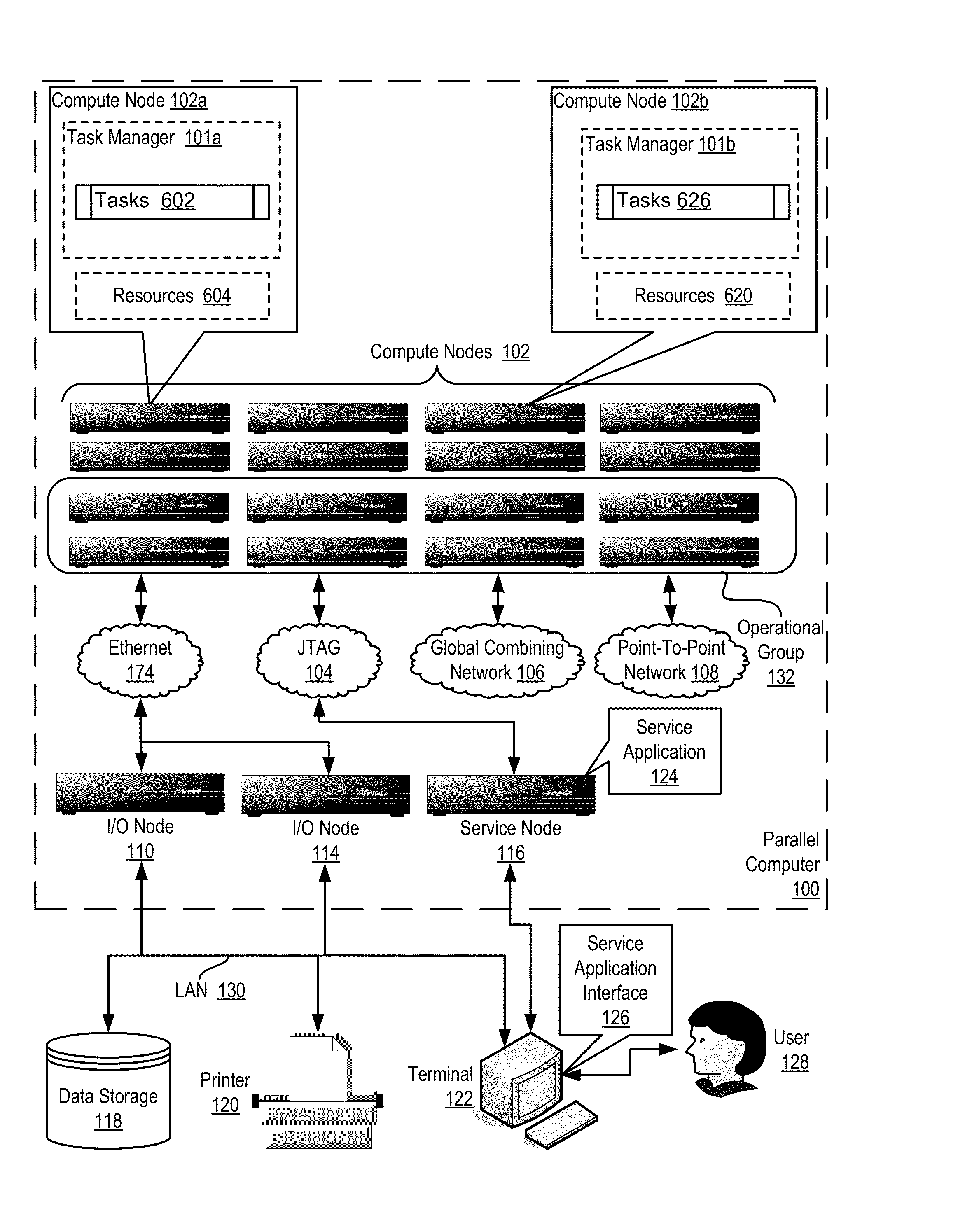
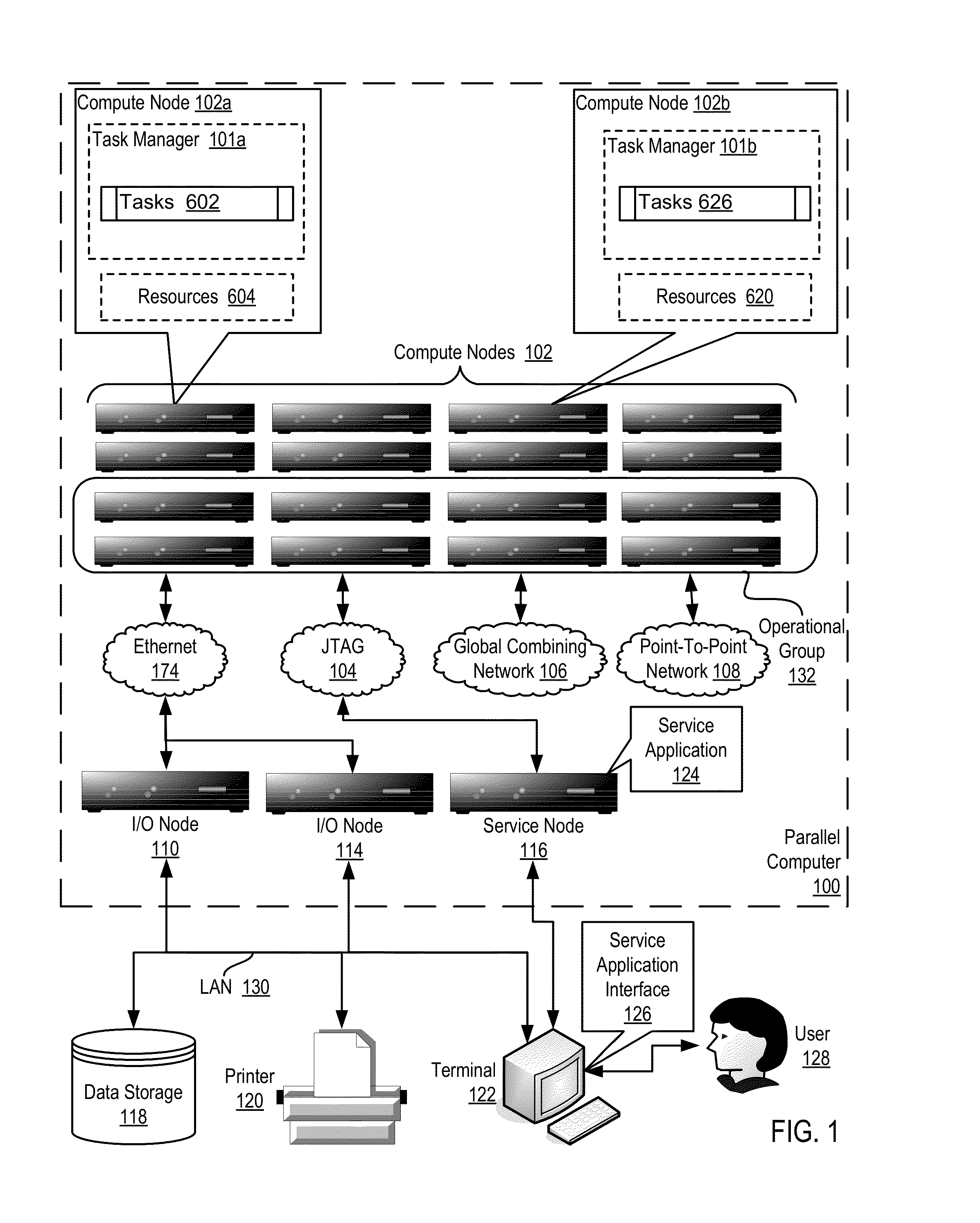
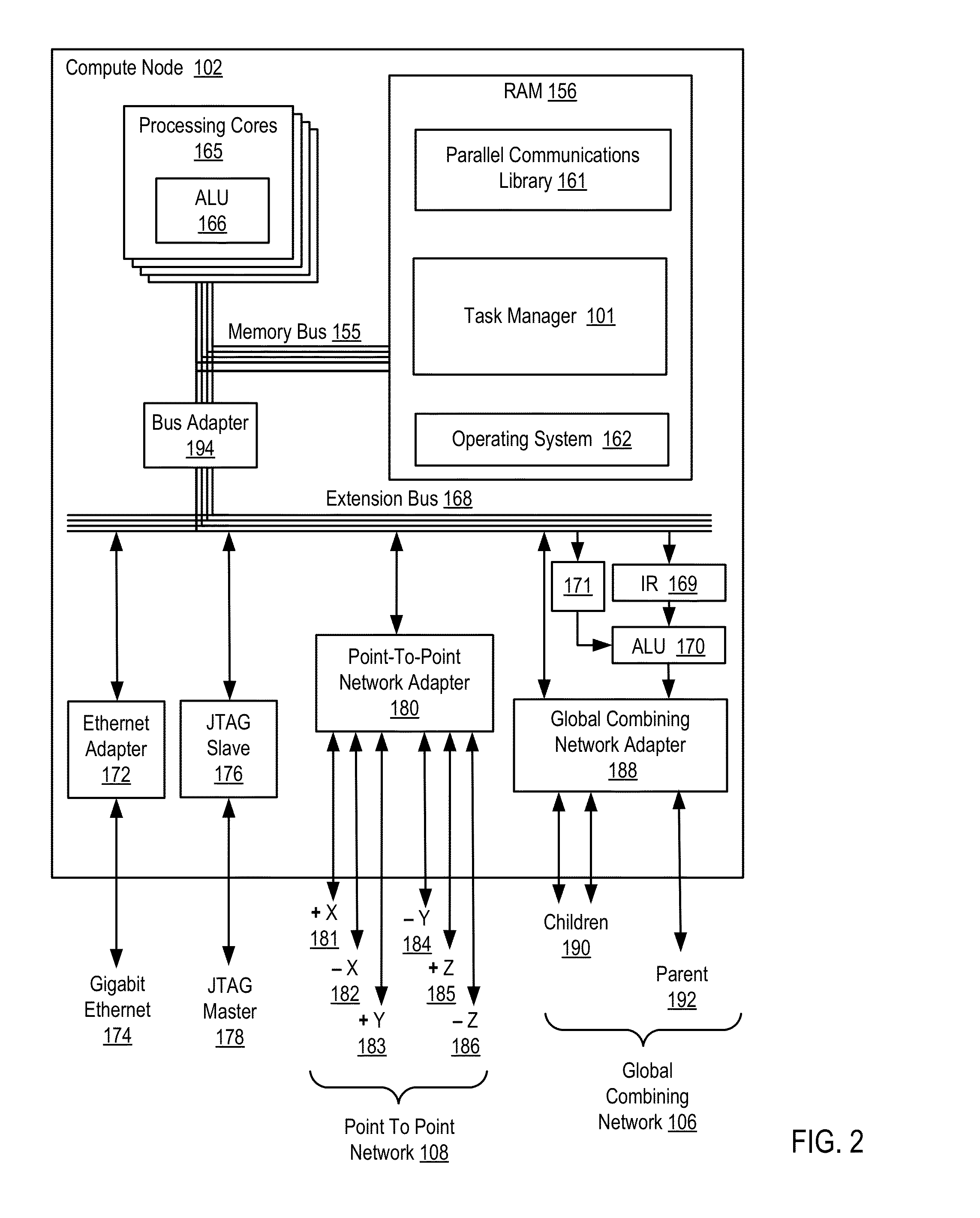
[0017]Exemplary methods, apparatus, and products for topology mapping in a distributed processing system in accordance with the present invention are described with reference to the accompanying drawings, beginning with FIG. 1. FIG. 1 sets forth example apparatus for topology mapping in a distributed processing system according to embodiments of the present invention. The apparatus of FIG. 1 includes a parallel computer (100), non-volatile memory for the computer in the form of a data storage device (118), an output device for the computer in the form of a printer (120), and an input / output device for the computer in the form of a computer terminal (122). The parallel computer (100) in the example of FIG. 1 includes a plurality of compute nodes (102). The compute nodes (102) are coupled for data communications by several independent data communications networks including a high speed Ethernet network (174), a Joint Test Action Group (‘JTAG’) network (104), a global combining network...


PUM


Abstract

Topology mapping in a distributed processing system, the distributed processing system including a plurality of compute nodes, each compute node having a plurality of tasks, each task assigned a unique rank, including: assigning each task to a geometry defining the resources available to the task; selecting, from a list of possible data communications algorithms, one or more algorithms configured for the assigned geometry; and identifying, by each task to all other tasks, the selected data communications algorithms of each task in a single collective operation.

Description

CROSS-REFERENCE TO RELATED APPLICATION[0001]This application is a continuation application of and claims priority from U.S. patent application Ser. No. 13 / 185,856, filed on Jul. 19, 2011.BACKGROUND OF THE INVENTION[0002]1. Field of the Invention[0003]The field of the invention is data processing, or, more specifically, methods, apparatus, and products for topology mapping in a distributed processing system.[0004]2. Description Of Related Art[0005]The development of the EDVAC computer system of 1948 is often cited as the beginning of the computer era. Since that time, computer systems have evolved into extremely complicated devices. Today's computers are much more sophisticated than early systems such as the EDVAC. Computer systems typically include a combination of hardware and software components, application programs, operating systems, processors, buses, memory, input / output devices, and so on. As advances in semiconductor processing and computer architecture push the performance...

Claims


Application Information

Patent Timeline
Patent Type & Authority Applications(United States)
IPC IPC(8): G06F9/46G06F15/16
CPCG06F9/5066G06F9/5072G06F9/546
Inventor ARCHER, CHARLES J.CAREY, JAMES E.MARKLAND, MATTHEW W.SANDERS, PHILIP J.
Owner INT BUSINESS MASCH CORP
Learn More