Autonomous cleaning appliance

Active Publication Date: 2013-03-14
DYSON TECH LTD
View PDF32 Cites 142 Cited by
  • Summary
  • Abstract
  • Description
  • Claims
  • Application Information

AI Technical Summary

Benefits of technology

[0018]Advantageously, this arrangement provides an autonomous appliance with a carrying arrangement that is unobtrusive to the user in the normal operation of the appliance since when in a stowed position it con

Problems solved by technology

In addition, the location of the separating apparatus means that it presents a resili

Method used


Image

  • Autonomous cleaning appliance
  • Autonomous cleaning appliance
  • Autonomous cleaning appliance

Examples


Embodiment Construction

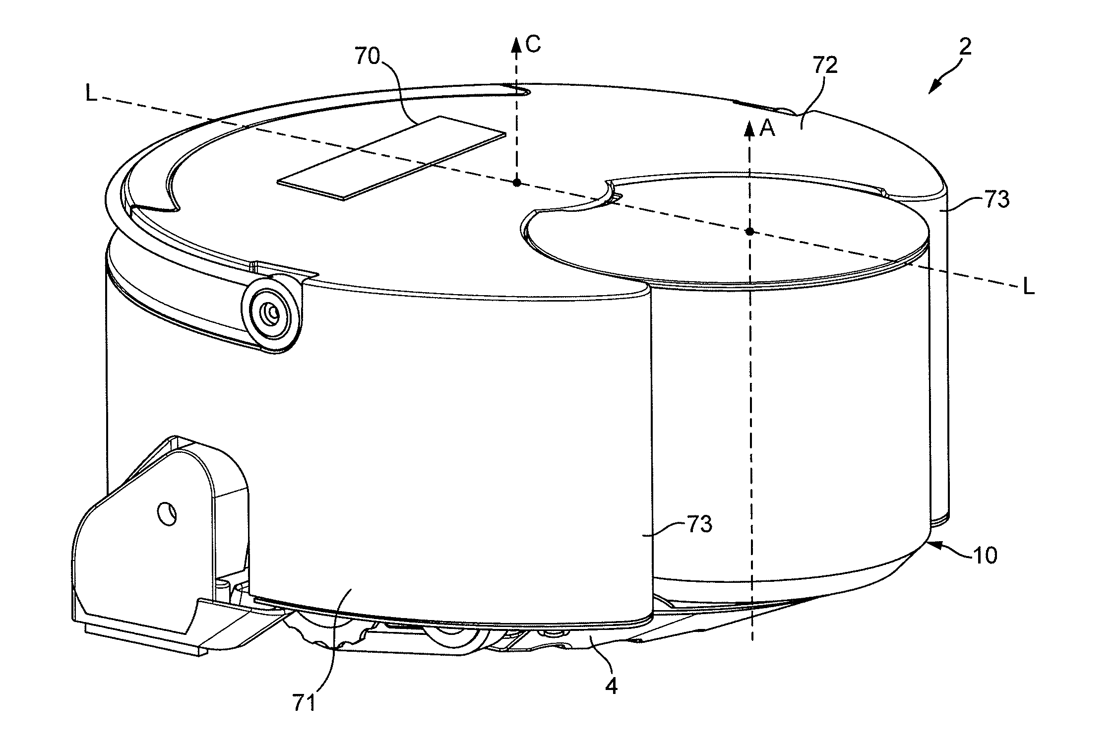
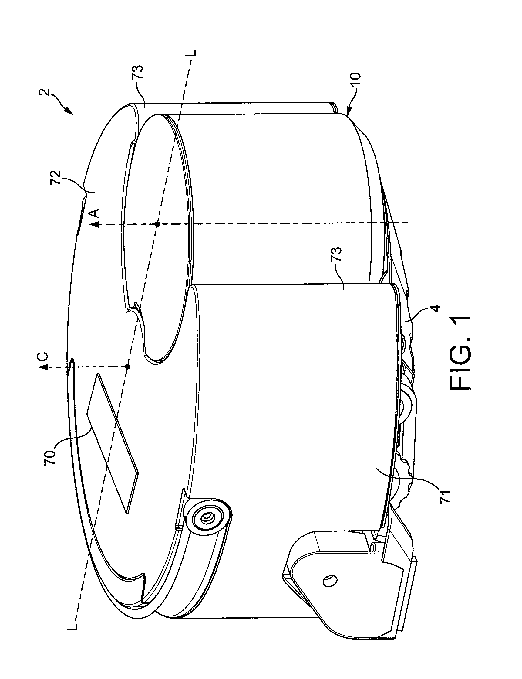
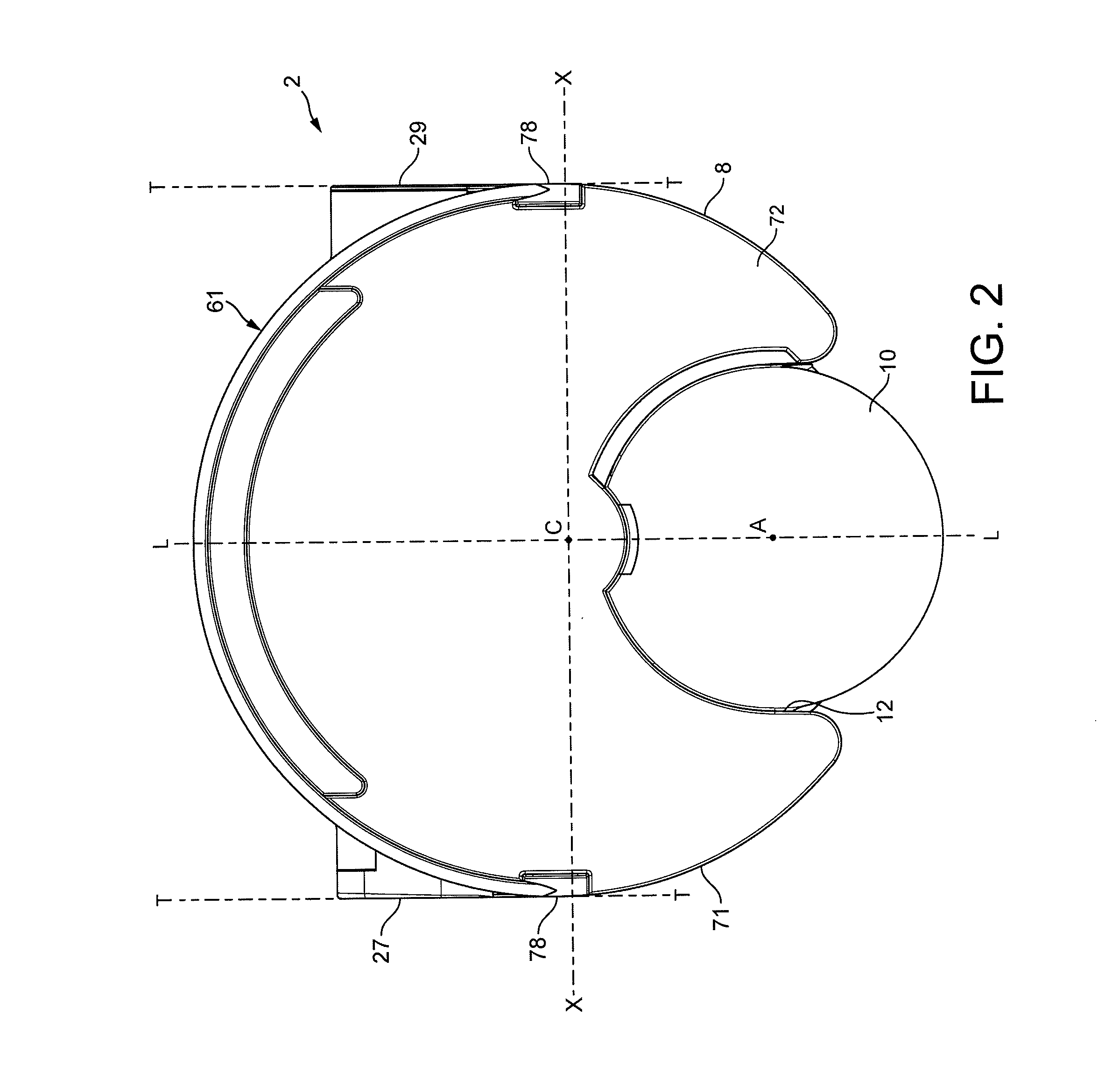
[0032]With reference to FIGS. 1, 2, 3 and 4 of the drawings, an autonomous surface treating appliance in the form of a robotic vacuum cleaner 2 (hereinafter ‘robot’) has a main body comprising four principal assemblies: a chassis (or sole plate) 4, a body 6 which is carried on the chassis 4, a generally circular outer cover 8 which is mountable on the chassis 4 and provides the main body of the robot 2 with a profile of a generally circular cylinder, and a separating apparatus 10 that is carried on a forward part of the body 6 and which protrudes through a complementary shaped cut-out 12 of the outer cover 8.

[0033]For the purposes of this specification, the terms ‘front’ and ‘rear’ in the context of the robot will be used in the sense of its forward and reverse directions during operation, with the separating apparatus 10 being positioned at the front of the robot. Similarly, the terms ‘left’ and ‘right’ will be used with reference to the direction of forward movement of the robot. ...


PUM


Abstract

An autonomous vacuum cleaner comprising a main body defining a first axis and housing a dirty air inlet, a clean air outlet, an airflow path between the dirty air inlet and the clean air outlet and a separating apparatus arranged in the air flow path between the dirty air inlet and the clean air outlet, the separating apparatus defining a second axis, wherein the separating apparatus is oriented so that the second axis is substantially parallel with the first axis of the main body and wherein a portion of the separating apparatus protrudes from a forward portion of the main body of the vacuum cleaner.

Description

REFERENCE TO RELATED APPLICATIONS[0001]This application claims the priority of United Kingdom Application No. 1115607.2, filed Sep. 9, 2011, the entire contents of which are incorporated herein by reference.FIELD OF THE INVENTION[0002]This invention relates to an autonomous cleaning appliance, and more specifically an autonomous or ‘robotic’ vacuum cleaner.BACKGROUND OF THE INVENTION[0003]Mobile robots are becoming increasingly commonplace and are used in such diverse fields as space exploration, lawn mowing and floor cleaning. The last decade has seen particularly rapid advancement in the field of robotic floor cleaning devices, especially vacuum cleaners, the primary objective of which is to navigate an area of a home or office autonomously and unobtrusively whilst cleaning the floor.[0004]A known self-guiding vacuum cleaner is exemplified in EP0803224, which vacuum cleaner includes a chassis supporting a housing with a cover and a front part which is movable with respect to the c...

Claims


Application Information

Patent Timeline
IPC IPC(8): A47L5/00
CPCA47L5/30A47L2201/00A47L9/1409A47L9/106
Inventor VANDERSTEGEN-DRAKE, MARK STAMFORDDYSON, JAMESBROWN, ANDRE DAVID
Owner DYSON TECH LTD
Why Eureka
Try Eureka