
Flat cable, cable harness using the same and method of making the flat cable

a flat cable and cable harness technology, applied in the field of flat cables, can solve the problems of wires that are peeled or fallen off from the wiring portion, and the resistance of wires in a width direction is not sufficient, and achieves the effect of improving the ability to follow the movemen

Inactive Publication Date: 2013-03-14
HITACHI METALS LTD
View PDF7 Cites 14 Cited by
  • Summary
  • Abstract
  • Description
  • Claims
  • Application Information

AI Technical Summary

Benefits of technology

The flat cable in this patent has the ability to stretch in its width direction, making it easier to wire on clothing or body. It also improves its ability to move along with the movement of the wiring portion. This results in a more comfortable and secure wiring experience. The cable is designed to be used in cable harnesses.

Problems solved by technology

Therefore, although the cable has relatively good resistance to tension in a longitudinal direction thereof since it is possible to move along with tension in the longitudinal direction, the wire does not have sufficient resistance to tension in a width direction of the cable (in an outer diameter direction) since it is not possible to move along with the tension in the width direction.
As a result, there are cases that the wiring material is peeled or fallen off from the wiring portion when tension is applied in a width direction of the cable.

Method used


Image

  • Flat cable, cable harness using the same and method of making the flat cable
  • Flat cable, cable harness using the same and method of making the flat cable

Examples


Embodiment Construction

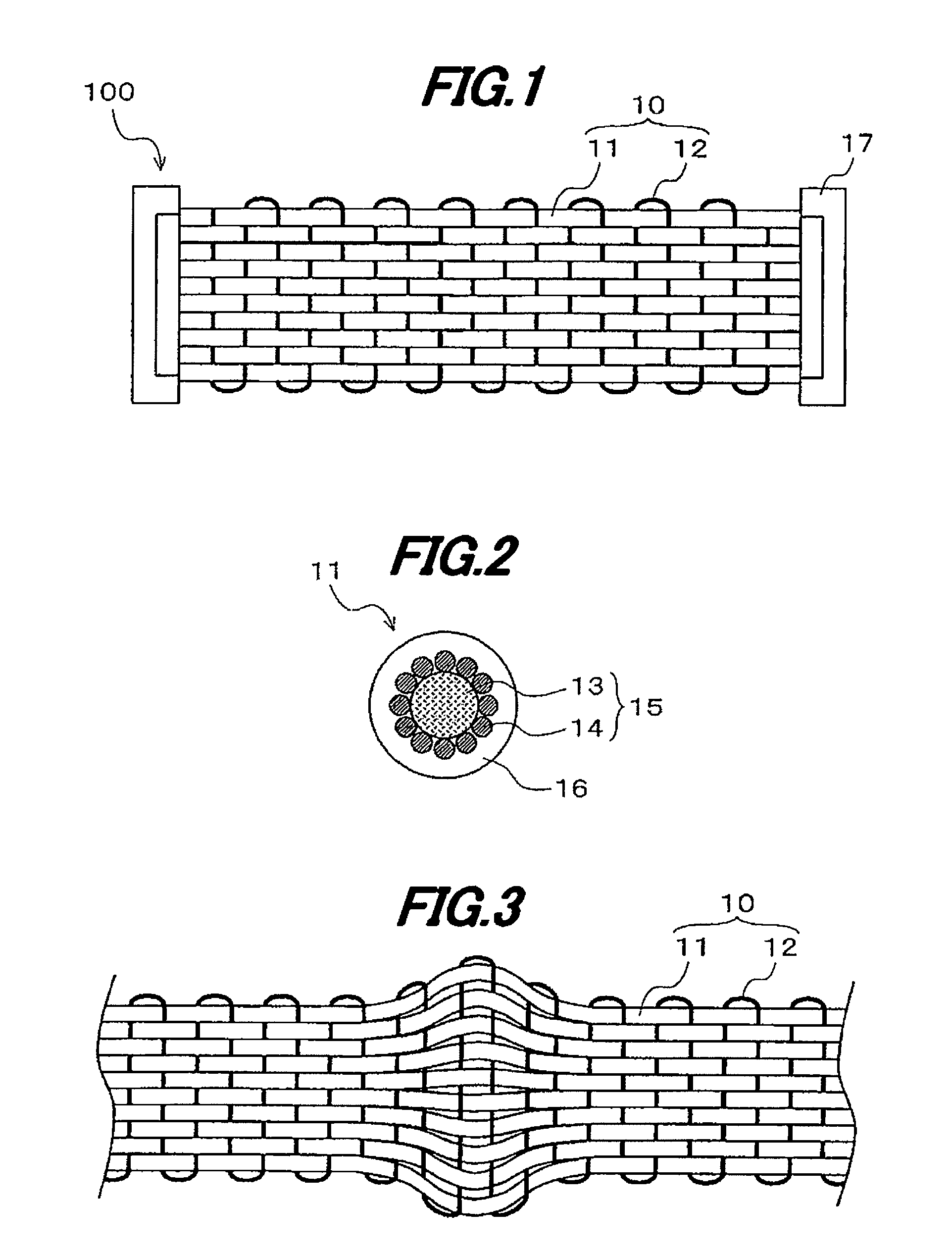
[0036]A preferred embodiment of the invention will be described below in conjunction with the appended drawings.

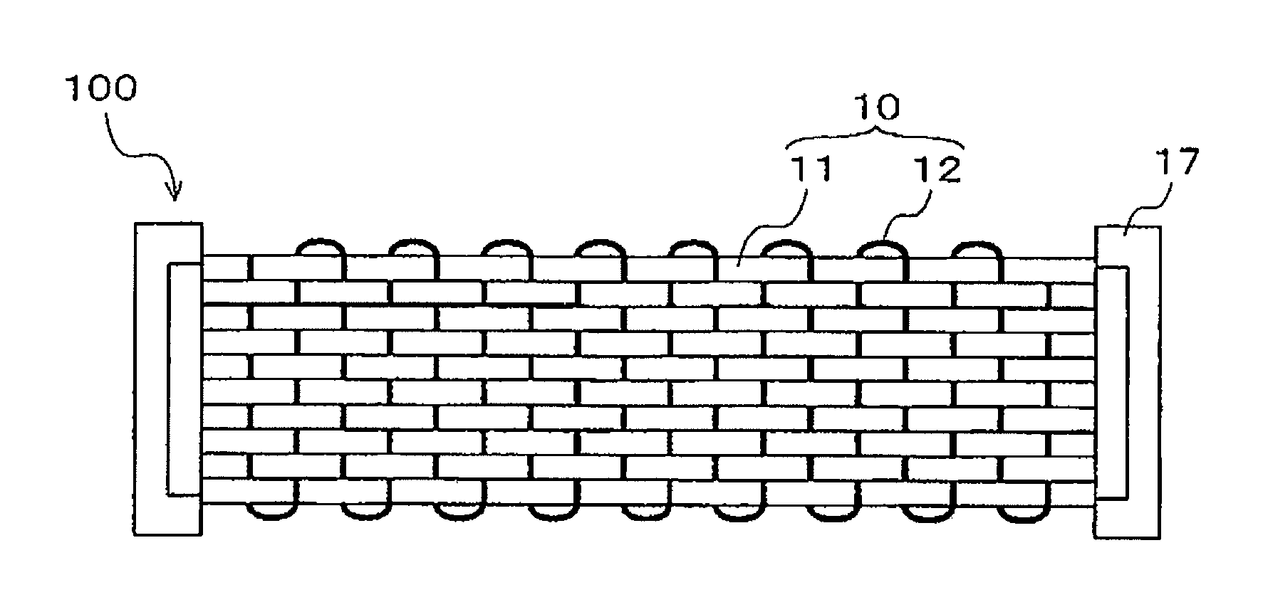
[0037]FIG. 1 is a plan view showing a cable harness using a flat cable in the embodiment.

[0038]As shown in FIG. 1, a flat cable 10 in the embodiment is provided with plural wires 11 arranged in parallel and a fibrous member 12 woven between (i.e., alternately over and under) the plural wires 11 along the arrangement direction (i.e., a direction substantially orthogonal to the longitudinal direction of the wires 11) of the wires 11.

[0039]As shown in FIG. 2, the wire 11 has an inner conductor 15 composed of a filament 13 formed of a tensile fiber or a fiber having stretching properties, etc., and plural conductors 14 spirally wound around an outer periphery of the filament 13, and an insulation 16 formed of a fluorine resin such as ethylene-tetrafluoroethylene copolymer (ETFE) which is formed on an outer periphery of the inner conductor 15.

[0040]The tensile fiber used for th...


PUM

PropertyMeasurementUnit
Forceaaaaaaaaaa
Forceaaaaaaaaaa
Forceaaaaaaaaaa

Abstract

A flat cable includes a plurality of wires arranged in parallel, and a fibrous member woven between the plurality of wires in the arrangement direction of the plurality of wires. The plurality of wires each include an inner conductor including a filament and a plurality of conductors on an outer periphery of the filament, and an insulation on an outer periphery of the inner conductor. The fibrous member includes a polyurethane elastic fiber.

Description

[0001]The present application is based on Japanese patent application No. 2011-198292 filed on Sep. 12, 2011, the entire contents of which are incorporated herein by reference.BACKGROUND OF THE INVENTION[0002]1. Field of the Invention[0003]The invention relates to a flat cable that is placed inside a body-worn device or a cloth attachment type device, a cable harness using the flat cable, and a method of making the flat cable.[0004]2. Description of the Related Art[0005]In recent years, according to the development of medical technology, physiological characteristics of human body measured by sensing the pulse or heart rate of human body using a sensor (IC chip) have been utilized for healthcare or diagnosis. For accurately sensing the pulse or heart rate of human body, there are body-worn devices or cloth attachment type devices in which a wiring material connecting a sensor to a measuring device is wired on a body or cloth so as to be in contact with human body.[0006]One of wiring...

Claims


Application Information

Patent Timeline
IPC IPC(8): H01B7/08H01B13/012
CPCH01B7/06Y10T29/49947H01B7/083
Inventor HUANG, DETIANWATANABE, TAKANOBUKOMURO, HIROSHI
Owner HITACHI METALS LTD
Learn More