Solid-liquid separation device

Active Publication Date: 2013-03-14
AMUKON +1
View PDF9 Cites 9 Cited by
  • Summary
  • Abstract
  • Description
  • Claims
  • Application Information

AI Technical Summary

Benefits of technology

[0011]In accordance with the present invention the movable members do not come into contact with the screw and therefore the movable members can be prevented from being rapidly worn out. Furthermore, since at least part of the movable members move, while penetrating closer to the center axis line of the screw than the outer circumferential edge of the screw blade, these movable members

Problems solved by technology

However, a problem associated with the solid-liquid separator of a contactless system is that the efficiency of liquid removal from the object to be treated is low and the object to be treated cannot be subjected to liquid removal treatment with good efficiency.
In the solid-liquid separator of a contactless system, where the movable members moving with respect to the fixed members interfere with the screw blade, the movable members are rapidly worn out or the movable members can be damaged by such interference.
Howeve

Method used


Image

  • Solid-liquid separation device
  • Solid-liquid separation device
  • Solid-liquid separation device

Examples


Example

[0060]The embodiments of the present invention will be described below in greater detail with reference to the appended drawings.

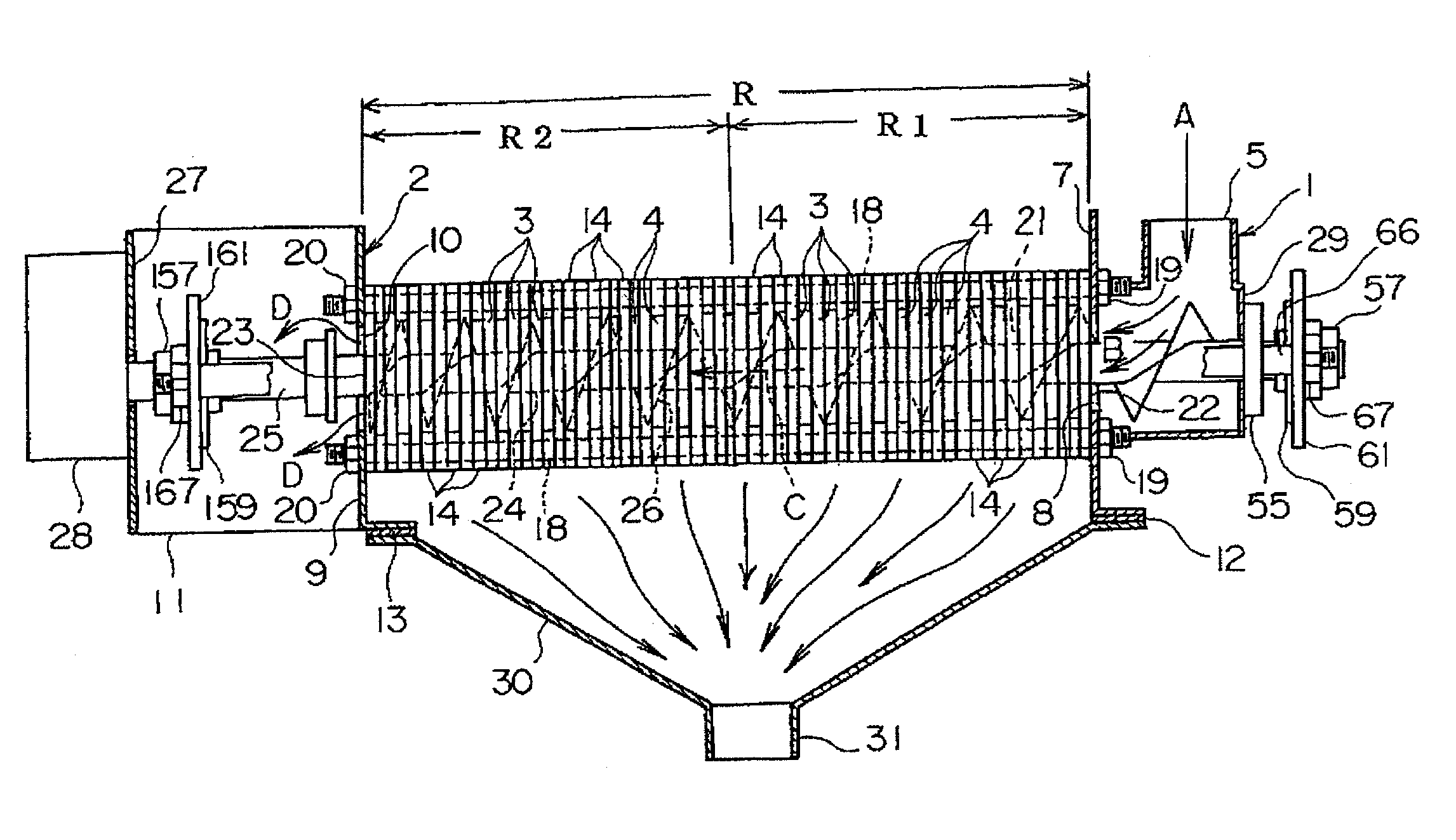
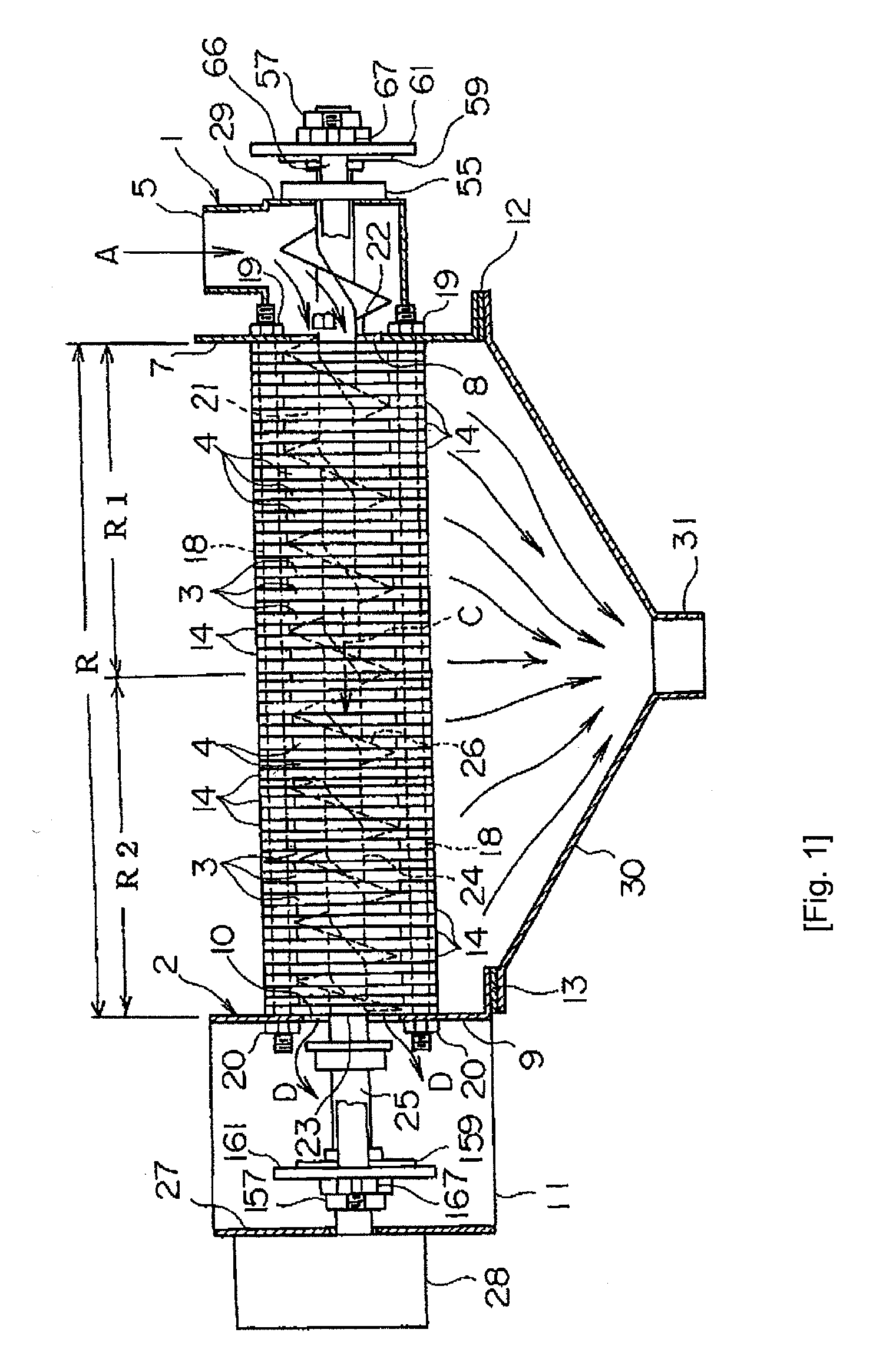
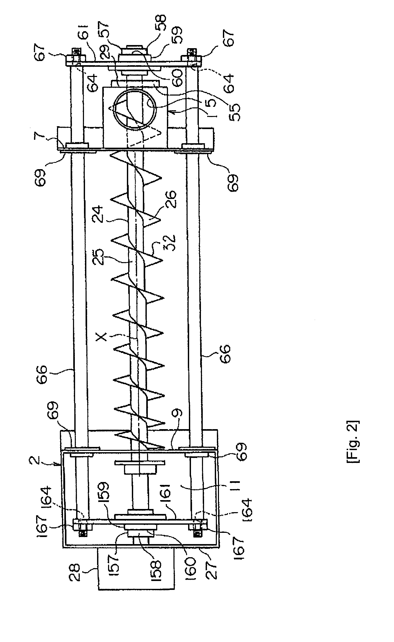
[0061]FIG. 1 is a front view, with a partial cross section, of a solid-liquid separator. FIG. 2 is a plan view of the solid-liquid separator. In this figure, the depiction of the below-describe fixed members and movable members is omitted. FIG. 3 is a perspective view illustrating part of the solid-liquid separator. The solid-liquid separator shown in these figures is suitable for solid-liquid separation of various treatment objects including a liquid, but the explanation below will be performed with reference to the case in which a sludge including a large amount of water is dewatered.

[0062]A solid-liquid separator of a contactless system shown in FIGS. 1 to 3 includes an inlet member 1 in which an inflow port 5 is formed in the upper portion and which is formed to have a hollow interior, an outlet member 2 having formed in the lower portion thereof a dis...


PUM

PropertyMeasurementUnit
Fractionaaaaaaaaaa
Ratioaaaaaaaaaa
Radiusaaaaaaaaaa

Abstract

A solid-liquid separation device includes a plurality of fixed members and movable members that are movably disposed between the adjacent fixed members, and a screw extending through the fixed members and the movable members in a state where the screw is not in contact with the fixed members and the movable members. The screw is rotationally driven about a center axis line thereof. A filtrate separated from an object is discharged to the outside of the solid-liquid separation portion through filtrate discharge gaps, and the object that has a reduced liquid content ratio is discharged from the outlet to the outside. In order to increase significantly a dewatering ratio, the movable members are formed to move while penetrating closer to the center axis line of the screw than an outer circumferential edge of the blade of the screw, without coming into contact with the screw.

Description

[0001]The present invention relates to a solid-liquid separation device / separator which includes a plurality of fixed members, a plurality of movable members that are disposed between the adjacent fixed members, and at least one screw extending through the fixed members and the movable members in a state where the screw is not in contact with the fixed members and the movable members, with this screw being rotationally driven about a center axis line thereof while an object to be treated that has penetrated into a solid-liquid separation portion demarcated by the fixed members and the movable members bring caused to move toward an outlet of the solid-liquid separation portion by rotation of the screw, and a filtrate separated from the object to be treated being discharged to the outside of the solid-liquid separation portion through filtrate discharge gaps between the fixed members and the movable members, and then the object to be treated that has a reduced water content ratio bein...

Claims


Application Information

Patent Timeline
IPC IPC(8): B30B9/12B01D25/127
CPCB01D29/35B01D29/46B01D29/52B30B9/121B30B9/12B30B9/26B01D25/127B01D29/6476B30B9/16B01D29/828B30B9/14
Inventor KANEKO, KAZUOTEZUKA, YUSUKENAKAMURA, YOSHITAKAKADOWAKI, YUKIKOBAYASHI, HIROKAZU
Owner AMUKON
Why Eureka
Try Eureka