Cube-sherman snake

a cube-sherman snake and cube-sherman technology, applied in the field of cube-sherman snakes, can solve the problems of difficulty in achieving the desired shape, unsatisfactory compromise, and sub-units not locked in this shape, and achieve good freedom of movemen

Inactive Publication Date: 2013-03-14
CUBE SHERMAN IP
View PDF27 Cites 15 Cited by
  • Summary
  • Abstract
  • Description
  • Claims
  • Application Information

AI Technical Summary

Benefits of technology

[0013]The present inventor has recognised that the aforementioned arrangement as illustrated in FIGS. 3a and 3b provides good freedom of movement such that the sub-units can be re-arranged so as to form a range of three-dimensional shapes. However, the arrangement has a drawback that w

Problems solved by technology

However, the arrangement has a drawback that when a desired shape is formed by manipulation and re-arrangement of the sub-units, the sub-units are not locked in this shape.
A further problem with the prior art arrangements is that as a user tries to manipulate the sub-units in order to achieve a desired shape, movement of one sub-unit can cause movement of other sub-units in the arrangement, which is frustrating and can lead to difficulties in achieving the desired shape.
As such, there is always an unsatisfactory compromise between providing a sufficiently high tension in th

Method used


Image

  • Cube-sherman snake
  • Cube-sherman snake
  • Cube-sherman snake

Examples


Embodiment Construction

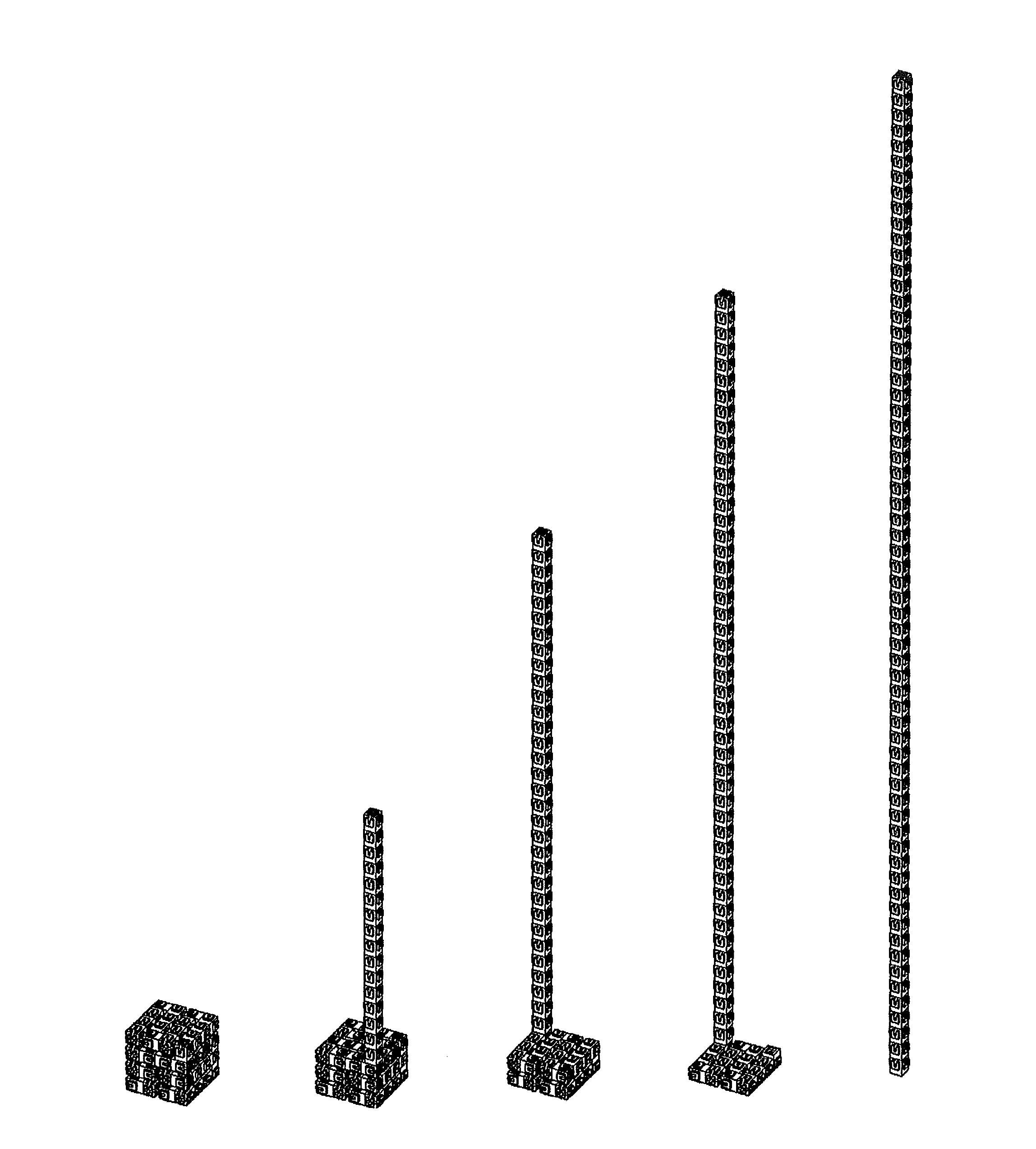
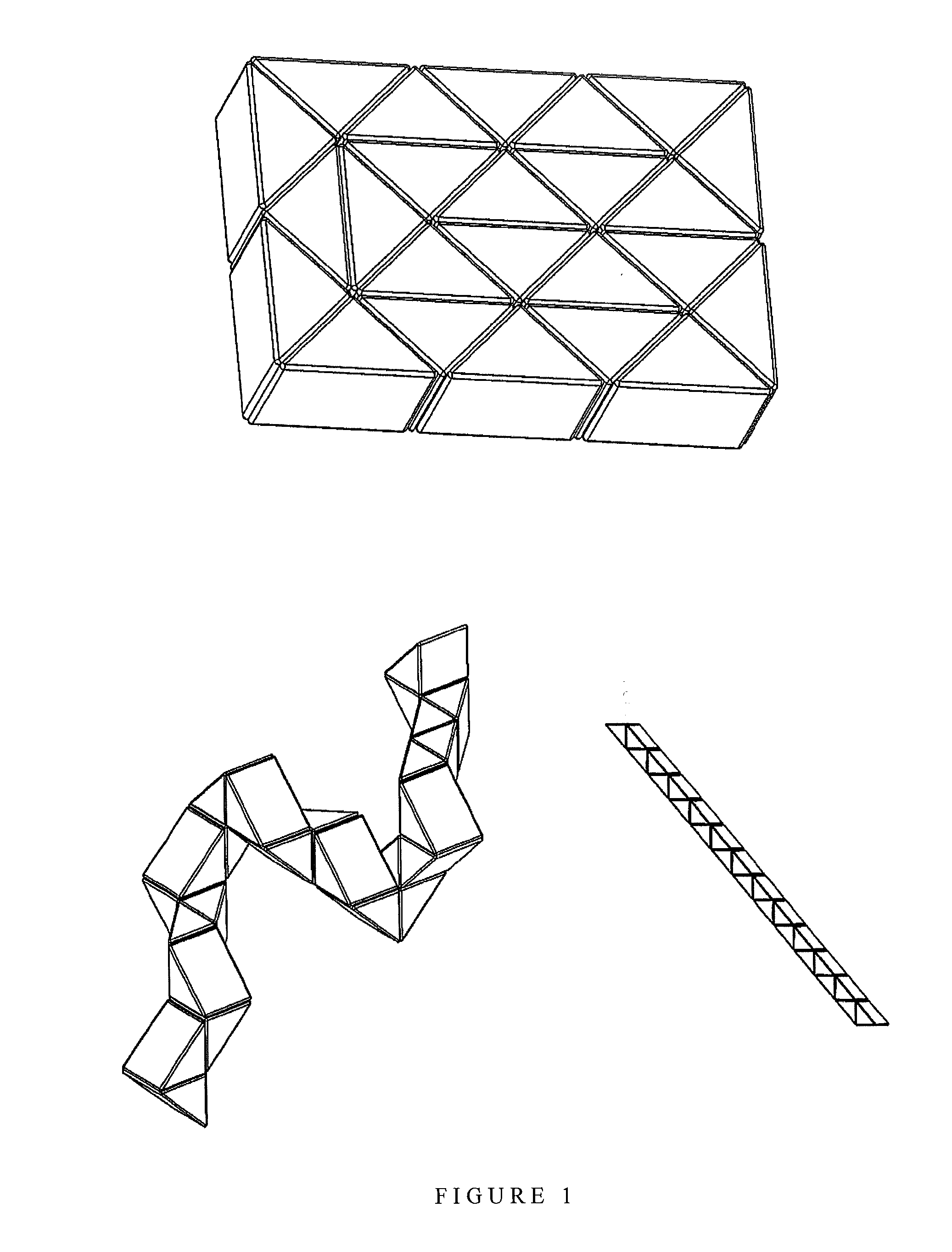
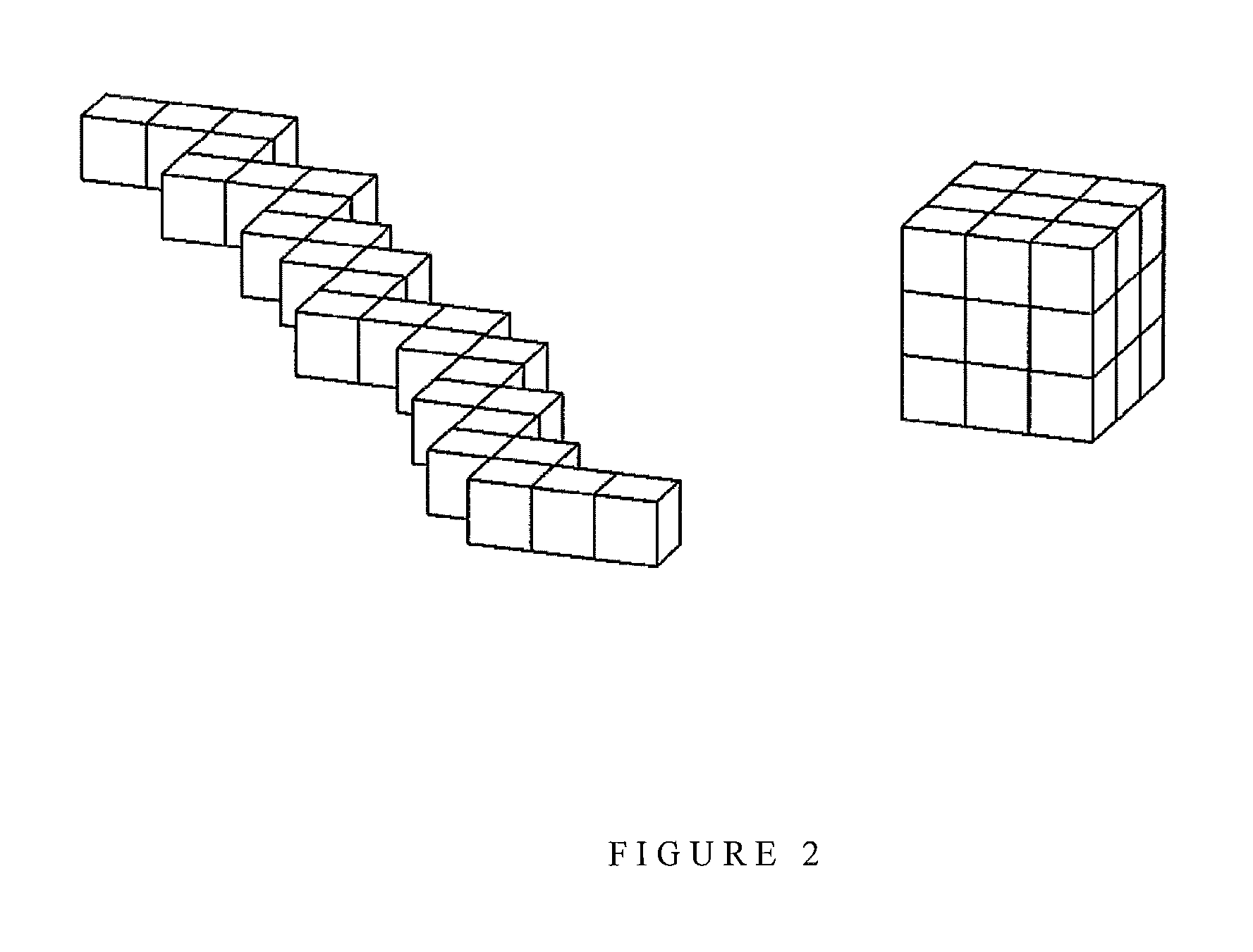
[0064]FIGS. 4a to 4d show a first embodiment of the present invention. The apparatus comprises a chain of sixty four sub-units connected together by an elastic biasing member passing through holes in the sub-units and being attached to end members of the chain. The elastic biasing member is under tension such that the sub-units are held together under compressive loading by the end members.

[0065]Each sub-unit is generally cubic in shape. Two perpendicular grooves are provided in a top face of each sub-unit forming a cross-shaped opening which extends down through the sub-unit to approximately half the height of the sub-unit. The sub-unit also comprises a hole which extends up from a bottom face and intersects the cross-shaped opening at a central point of the sub-unit.

[0066]Each sub-unit further comprises a square-shaped recess in a bottom face. Square-shaped projections are provided on each of the side faces and in the top face. These square shaped projections are complementary in ...


PUM


Abstract

An apparatus comprising: a plurality of sub-units; and one or more connecting members for connecting the plurality of sub-units together in a chain, wherein the plurality of sub-units is held together in the chain by the one or more connecting members disposed between the sub-units, wherein each sub-unit comprises at least one groove through which the connecting member, or one of the connecting members, is movable to allow adjacent sub-units to be rotated around at least one rotational axis relative to each other by a user, and wherein the apparatus further comprises a locking mechanism to lock adjacent sub-units together resisting rotation and resisting disengagement.

Description

FIELD OF INVENTION[0001]The present invention relates to an apparatus which can be manipulated into different configurations. The apparatus comprises a plurality of sub-units connected and held together by one or more connecting members. The sub-units may be rotated so as to be in different relative orientations while remaining in the same physical locations. Furthermore, the sub-units may be pulled apart and moved so as to be in different physical locations relative to each other.[0002]The present inventor has realized that it would be desirable to create a medium for constructing spatial constructions, sculptural assemblages which can combine aesthetic appeal and fun. The present inventor has also realized that such a combination of aesthetics and play will have a particular appeal to children, encouraging them to experiment with sculpture and architectonics to increase visual and spatial awareness, manual dexterity, and logical and creative thinking.[0003]Certain embodiments of t...

Claims


Application Information

Patent Timeline
IPC IPC(8): A63F9/06
CPCA63F9/0876A63H33/102A63F2009/0888A63F9/088A63H33/103E04C1/00
Inventor CUBE-SHERMAN, GIDEON
Owner CUBE SHERMAN IP
Why Eureka
Try Eureka