Display processing apparatus, image forming system, display processing method, and computer-readable storage medium
a display processing and display technology, applied in the field of display processing apparatus, image forming system, display processing method, computer-readable storage medium, can solve the problems of inability to realize the preview display near to the actual print result, the difference between the actual print result and the preview display becomes large,
- Summary
- Abstract
- Description
- Claims
- Application Information
AI Technical Summary
Benefits of technology
Problems solved by technology
Method used
Image
Examples
first embodiment
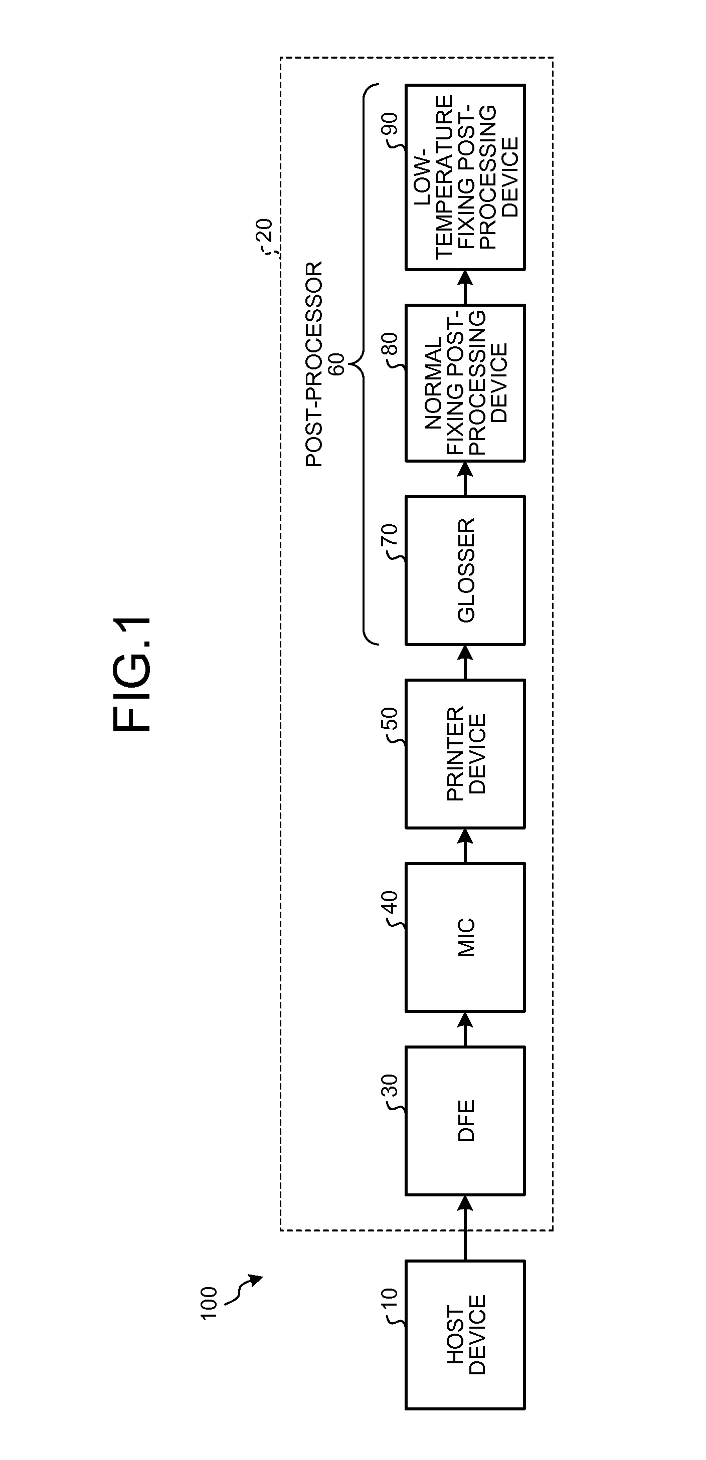
[0051]FIG. 1 is a block diagram illustrating of an example of a schematic configuration of an image forming system 100 according to the embodiment. As illustrated in FIG. 1, the image forming system 100 includes a host device 10 and a printing apparatus 20.
Configuration of Printing Apparatus
[0052]For the convenience of explanation, first, a specific configuration of the printing apparatus 20 will be explained. The printing apparatus 20 is configured by connecting a digital front end (DFE) 30, a mechanism I / F controller (MIC) 40, a printer device 50, a post-processor 60.
[0053]The DFE 30 communicates with the printer device 50 via the MIC 40 and controls image formation in the printer device 50. Further, the DFE 30 is connected with the host device 10 to be described later. The DFE 30 receives print data to be described from the host device 10 and generates image data for forming a toner image according to respective CMYK toners and a colorless (transparent color) clear toner based on...
second embodiment
[0146]Next, a second embodiment will be explained. In the second embodiment, a table number is specified according to device configuration information and number of times information to be described later and a surface effect selection table corresponding to the table number is disposed to each of the host device 10 and the DFE 30. Hereinafter, a portion different from the first embodiment will be mainly described. A portion common to the first embodiment is denoted by the same reference numeral and an explanation thereof is appropriately omitted.
[0147]FIG. 24 is a view illustrating an example of a schematic configuration of a printing apparatus 20 of the second embodiment. As illustrated in FIG. 24, the printing apparatus 20 includes a first conveying path 150, a second conveying path 160, and a switching unit 170. The first conveying path 150 is a conveying path for conveying a recording medium from the printer device 50 to the post-processor 60 and conveying the recording medium ...
third embodiment
[0168]In respective embodiments described above, although the host device 10 is configured to execute the preview image display process, the embodiments are not limited thereto.
[0169]That is, the embodiments may be configured such that any of plural processes executed by a device is executed by at least a device connected to the device via a network.
[0170]As an example of the configuration, an image forming system according to the embodiment mounts a part of a function of a host device on a server device on a network.
[0171]FIG. 30 is a view exemplifying a configuration of an image forming system 100D according to the embodiment. As illustrated in FIG. 30, the image forming system 100D includes a host device 110 and the printing apparatus 20.
[0172]The embodiment is configured such that the host device 110 is connected to a server device 3060 via a network such as the Internet, and the like. Further, in the embodiment, functions of a plane data generating unit 122, a print data genera...
PUM
 Abstract
Description
Claims
Application Information
 - R&D
- Intellectual Property
- Life Sciences
- Materials
- Tech Scout
- Unparalleled Data Quality
- Higher Quality Content
- 60% Fewer Hallucinations
Browse by: Latest US Patents, China's latest patents, Technical Efficacy Thesaurus, Application Domain, Technology Topic, Popular Technical Reports.
© 2025 PatSnap. All rights reserved.Legal|Privacy policy|Modern Slavery Act Transparency Statement|Sitemap|About US| Contact US: help@patsnap.com


