Spacecraft thruster

a thruster and spacecraft technology, applied in the field of spacecraft thrusters, can solve the problems of reducing affecting the efficiency of spacecraft thrusters, and requiring a very high voltage between the accelerating grids,

Inactive Publication Date: 2013-03-21
ELWING LLC
View PDF1 Cites 25 Cited by
  • Summary
  • Abstract
  • Description
  • Claims
  • Application Information

AI Technical Summary

Benefits of technology

[0046]the thruster comprises at least a second magnetic field generator adapted to generate a second magnetic field

Problems solved by technology

One of the problems of this type of device is the need for a very high voltage between the accelerating grids.
Another problem is the erosion of the grids due to the impact of ions.
Last, n

Method used


Image

  • Spacecraft thruster
  • Spacecraft thruster
  • Spacecraft thruster

Examples


Embodiment Construction

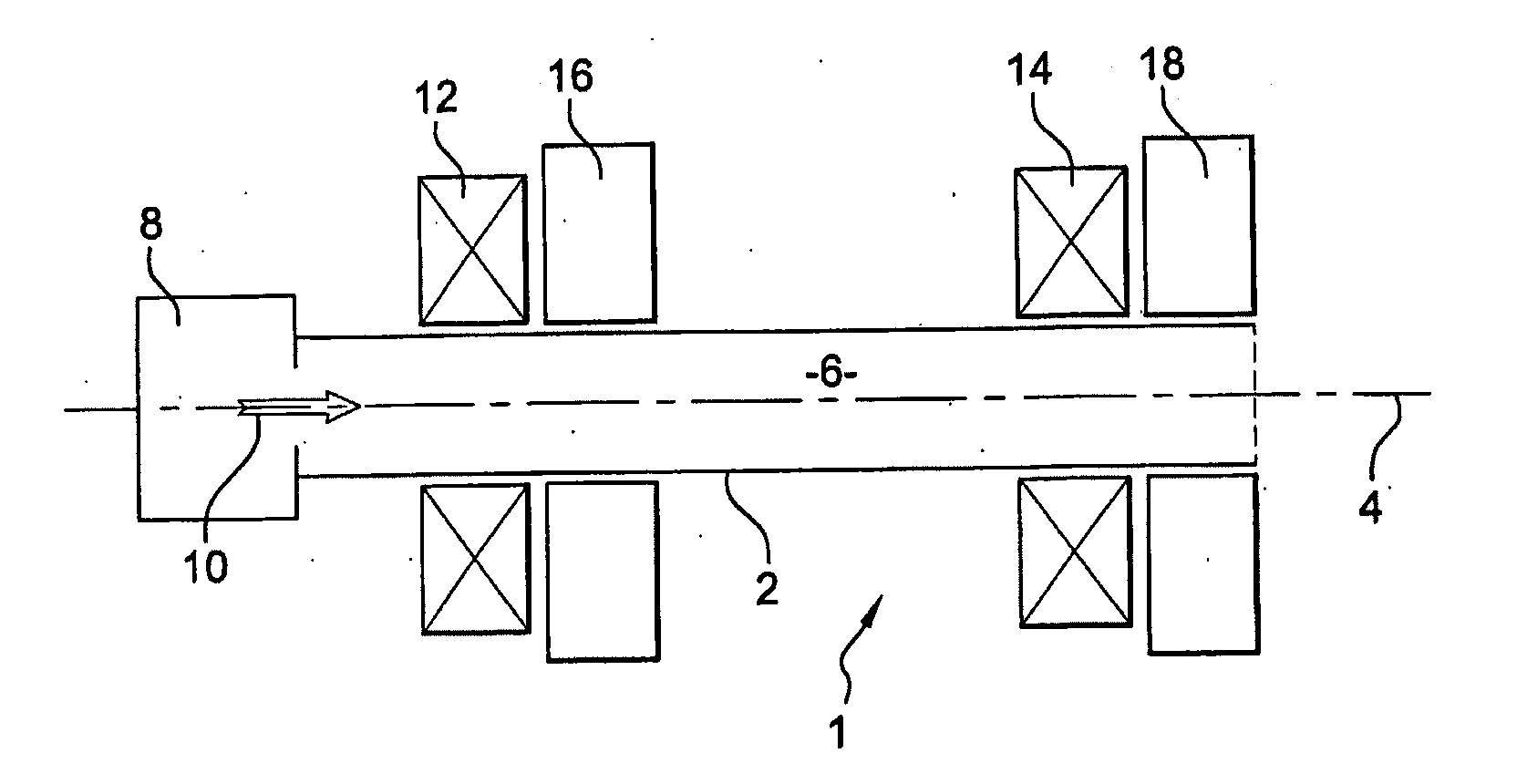
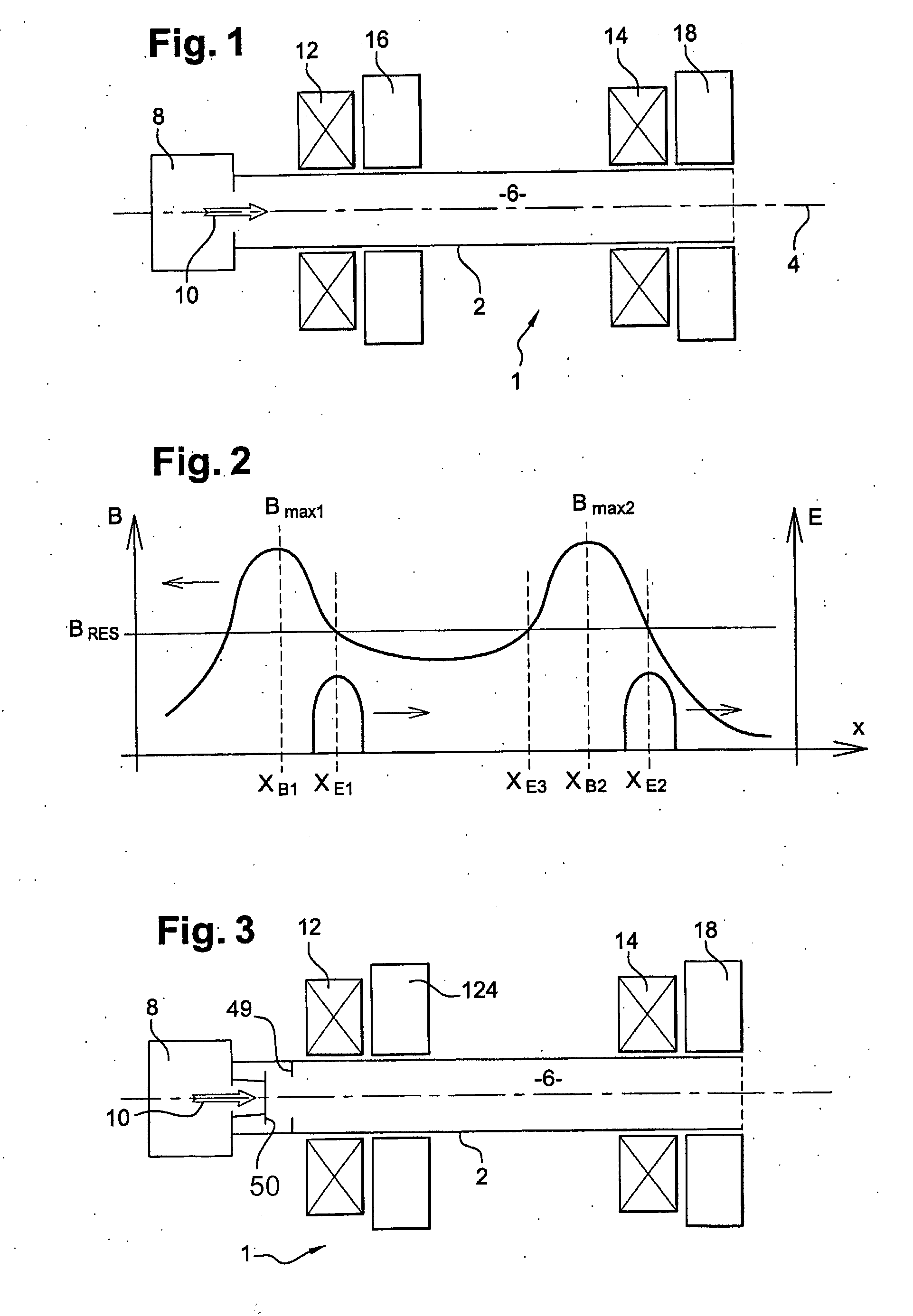
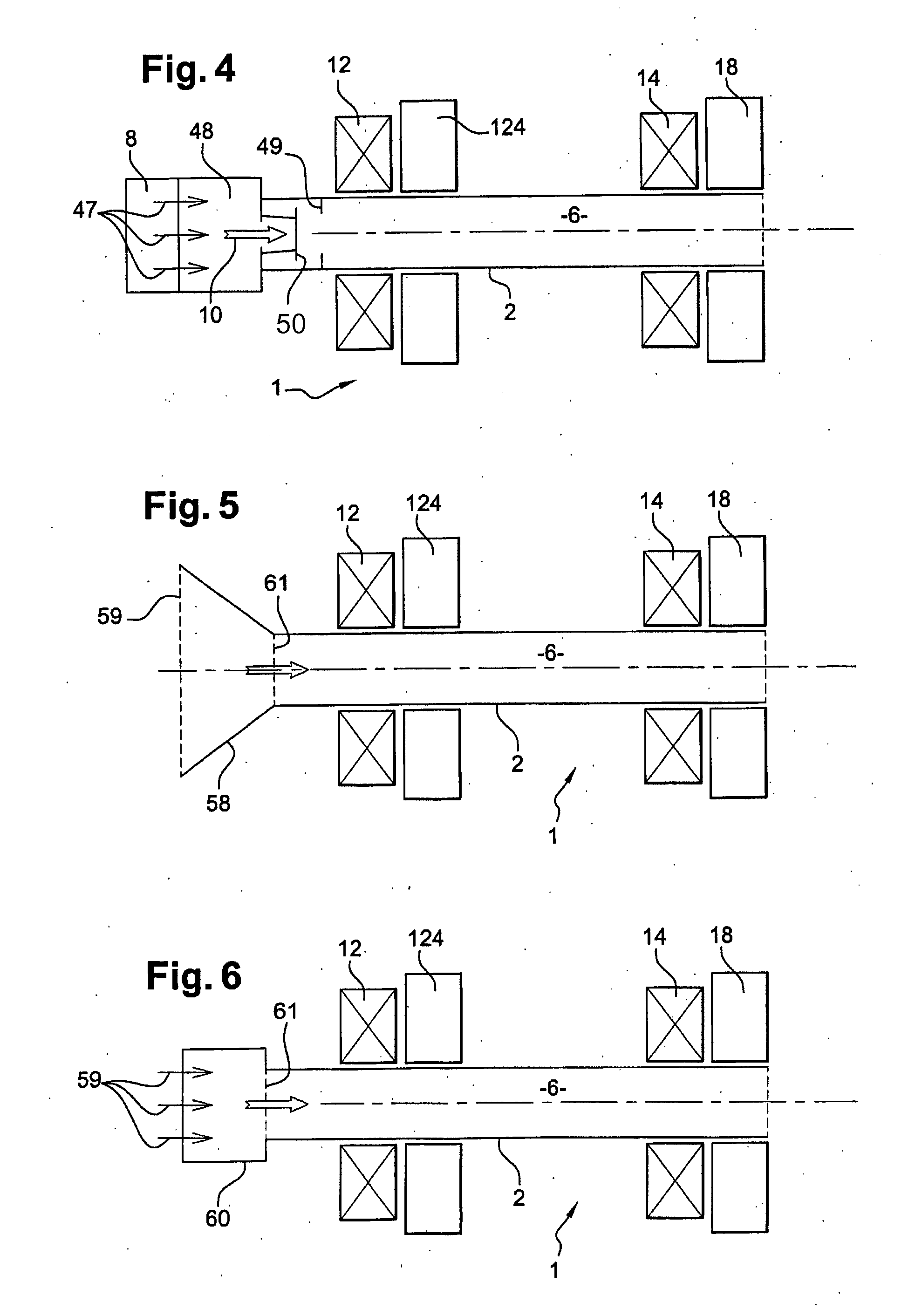
[0223]European patent application EP-03290712 discloses a thruster using ponderomotive force thrust. FIG. 1 is a schematic view in cross-section of a thruster. The thruster 1 of FIG. 1 relies on electron cyclotron resonance for producing a plasma, and on magnetized ponderomotive force for accelerating this plasma for producing thrust. The ponderomotive force is the force exerted on a plasma due to a gradient in the density of a high frequency electromagnetic field. In the absence of a magnetic field, this force may be expressed as:

F=-q24mω2∇E2foroneparticuleF=-ωp22ω2∇ɛ0E22fortheplasmawithωp2=ne2meɛ0

[0224]In presence of a non-uniform magnetic field this force can be expressed as:

F=-q24mω(∇E2(ω-Ωc)-E2(ω-Ωc)2∇Ωc)-μ∇B

[0225]The device of FIG. 1 comprises a tube 2. The tube has a longitudinal axis 4 which defines an axis of thrust; indeed, the thrust produced by the thruster 1 is directed along this axis—although it may be guided as explained below in reference to FIGS. 10 to 13. The insi...


PUM


Abstract

A thruster (1) has a main chamber (6) defined within a tube (2). The tube has a longitudinal axis which defines an axis (4) of thrust; an injector (8) injects ionizable gas within the tube, at one end of the main chamber. An ionizer (124) is adapted to ionize the injected gas within the main chamber (6). A first magnetic field generator (12, 14) and an electromagnetic field generator (18) are adapted to generate a magnetized ponderomotive accelerating field downstream of said ionizer (124) along the direction of thrust on said axis (4). The thruster (1) ionizes the gas, and subsequently accelerates both electrons and ions by the magnetized ponderomotive force.

Description

CROSS-REFERENCE TO RELATED APPLICATIONS[0001]This application is a continuation-in-part of U.S. patent application Ser. No. 11 / 663,025 filed on Mar. 15, 2007.BACKGROUND AND SUMMARY OF THE INVENTION[0002]The invention relates to the field of thrusters. Thrusters are used for propelling spacecrafts, with a typical exhaust velocity ranging from 2 km / s to more than 50 km / s, and density of thrust below or around 1 N / m2. In the absence of any material on which the thruster could push or lean, thrusters rely on the ejection of part of the mass of the spacecraft. The ejection speed is a key factor for assessing the efficiency of a thruster, and should typically be maximized.[0003]Various solutions were proposed for spatial thrusters. U.S. Pat. No. 5,241,244 discloses a so-called ionic grid thruster. In this device, the propelling gas is first ionized, and the resulting ions are accelerated by a static electromagnetic field created between grids. The accelerated ions are neutralized with a f...

Claims


Application Information

Patent Timeline
IPC IPC(8): F03H1/00
CPCF03H1/0081
Inventor EMSELLEM, GREGORYLARIGALDIE, SERGE
Owner ELWING LLC
Why Eureka
Try Eureka