Vortex flow meter

a flow meter and vortex technology, applied in the direction of volume/mass flow by dynamic fluid flow effect, measurement devices, instruments, etc., can solve the problems of reducing the performance characteristics of the sensor, low force applied, and sensor type cannot be used to measure the flow velocity of process fluid, so as to improve the uniformity of vortex formation, reduce cross sectional flow area, and enhance the effect of eliminating common mode influences

Inactive Publication Date: 2013-03-21
AVGI ENG
View PDF4 Cites 0 Cited by
  • Summary
  • Abstract
  • Description
  • Claims
  • Application Information

AI Technical Summary

Benefits of technology

[0020]Additionally, the flow conduit of the flow meter may comprise first and second flat surfaces at the first and second interfaces of said vortex generator and said flow conduit, the first and second flat surfaces terminating at the extremities of said flow conduit. The first and second flat surfaces being parallel and having a chordal width equal or less than W, wherein W is defined by W=(0.4*pipe inside diameter+0.94) expressed in inches. The first and second flat surfaces are interconnected by portions of a first and second cylindrical surface of said body thereby providing improved uniformity of vortex formation. A lower flow limit is achieved due to the reduced cross sectional flow area of said flow conduit increasing the velocity within the flow conduit with respect to average pipeline flow.
[0021]In another aspect the flow meter may have a circuit capable of electronic signal conditioning and amplification. The circuit may include a means for automatically and constantly assuring the absolute electrical signal level response of each of the said force sensors for equal inputs is equal thereby resulting in enhanced elimination of common mode influences is achieved.

Problems solved by technology

This type of sensor cannot be used for measuring the flow velocity of process fluids at extreme temperatures mainly due to the operating temperature limitations of fill fluids and conventional piezoelectric elements used in these types of sensors.
The motion of the paddle is transmitted by a lever of relatively low stiffness compared to the piezoelectric sensor which results in a low force applied to the piezoelectric sensor thereby reducing the performance characteristics of the sensor.
This design is further flawed, however, in that if the reduced thickness portion of the conduit fails to contain high process pressures and / or hazardous fluids.
Thus present vortex flow meters with either the sensor located within the flow conduit or external to the flow conduit have concerns that are not addressed.
Furthermore, most of the existing vortex flow meters do not provide a redundant measurement option in a wafer form for the relatively large components cannot be located within the bolt pattern required for wafer configuration.
Redundant sensing requires costly-flanged dual meters or a much more costly-flanged dual in-line meter.
The dual in-line meters require two flow K-factors and have increased pressure drop causing greater pumping losses.

Method used


Image

  • Vortex flow meter
  • Vortex flow meter
  • Vortex flow meter

Examples


Embodiment Construction

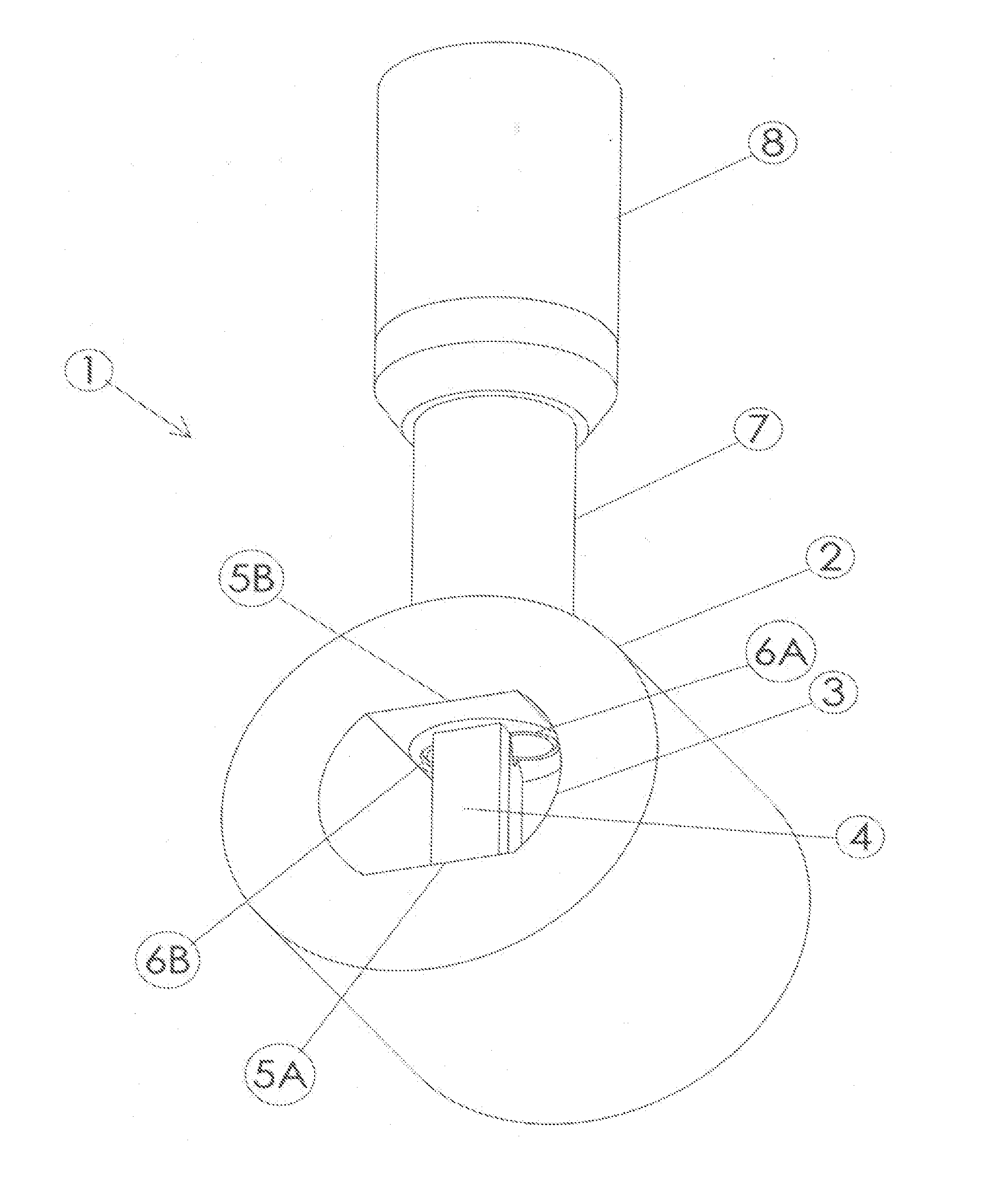
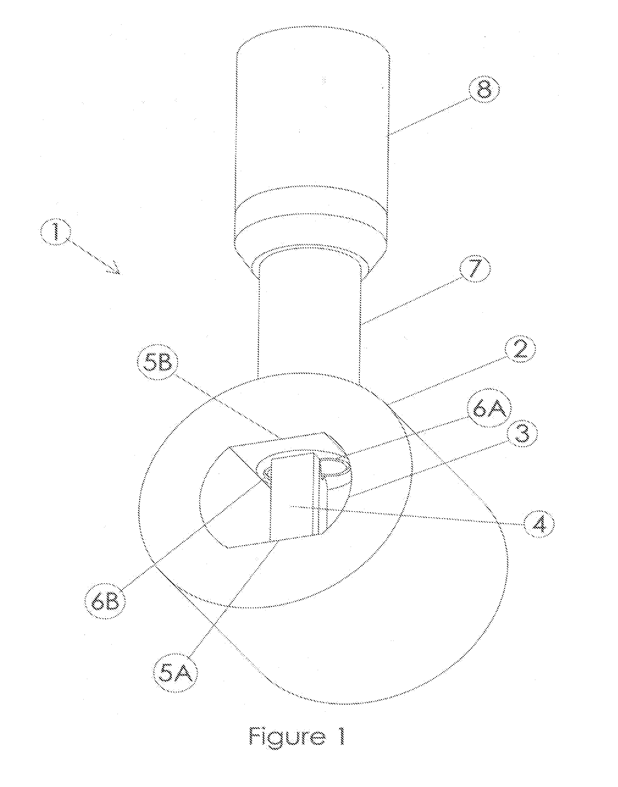
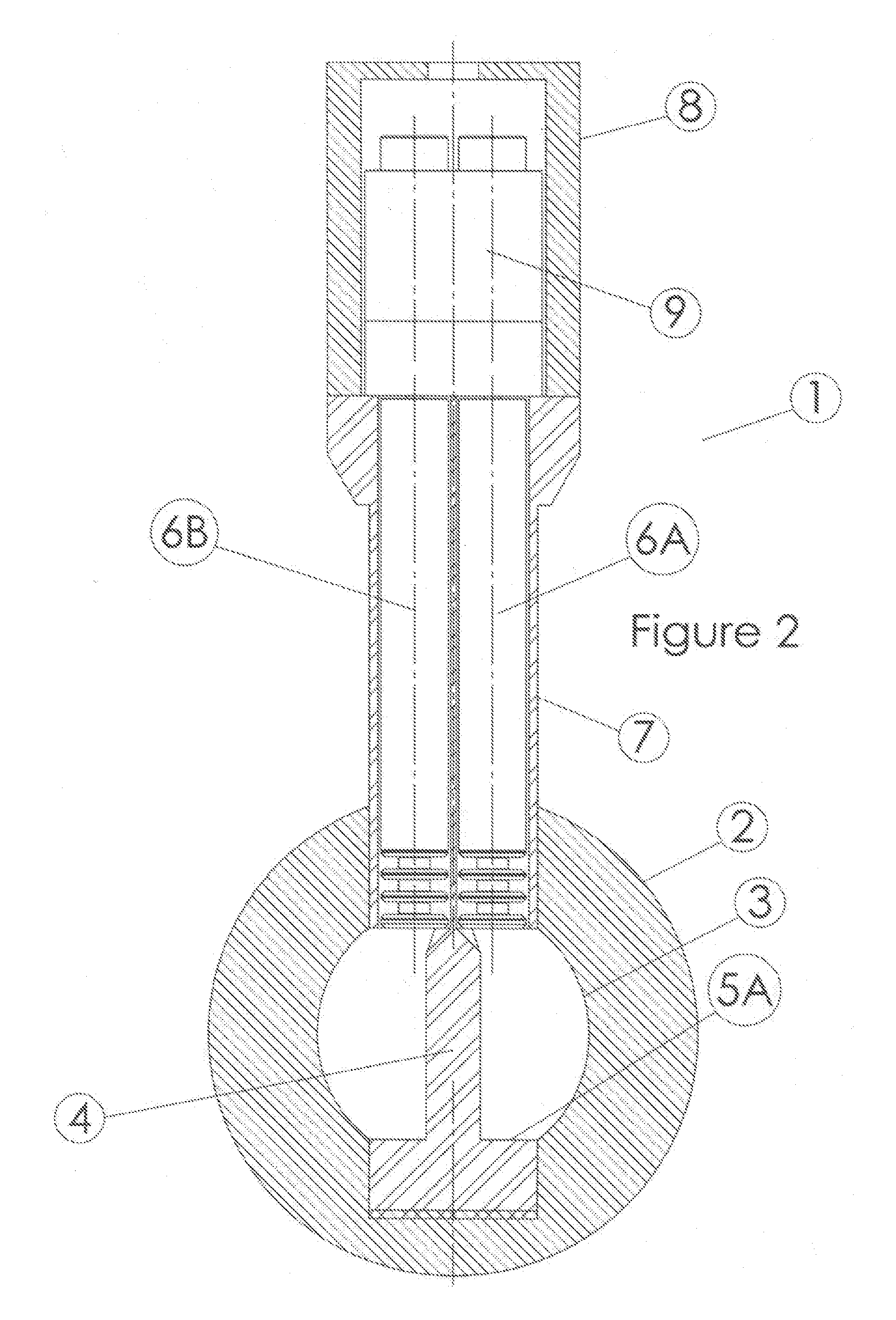
[0041]A vortex flow meter having many benefits is disclosed. The benefits are based and derived from a proven principle of conservation of energy that assures a maximum amount of the available energy of the input signal is applied to the sensor. This invention assures that the available signal is transferred effectively to a sensor located outside the flow conduit to within 97% of available energy of the input signal.

[0042]This effectiveness is achieved by use of a pressure to uniaxial force transducer that has no springs or levers. Springs and levers are not effective for an undesired deflection with applied loads diminishes the energy available to the sensor.

[0043]The varying pressure of vortices being shed from the vortex generator provides the energy. The varying pressure of vortices is described in the referenced article ASME Publication 78-WA / FM-3. This pressure is applied to the effective area of a diaphragm or a bellows and produces a force (Ft) that is transmitted by a colu...


PUM


Abstract

A vortex flow meter that senses the alternating pressure variations generated by a fixed vortex shedding generator. The alternating pressure variations of the vortices within the rows on each side of the vortex shedding generator act upon flexible elements producing forces on long columns that are transmitted to remotely located piezoelectric force sensors. The alternating forces upon the two columns are used to determine the passage of a vortex and thereby the flow. Improved output signal by minimizing loss of parasitic energy. 97% of the available signal is applied to the piezoelectric force sensors as compared to conventional 60%. Process influences such as vibration in all planes and pumping pulsations are equal and opposing and are rejected by the sensor. A capability of operating at extreme process temperatures is assured for the high temperature of the process is dissipated to the environment along the long columns. Reliability of operation is assured for the sensor has no process seals and is easily replaced by technicians, without interrupting flow or venting process. Improved process containment is realized with construction having a high safety factor and multiple stages of process containment. Wafer form reduces installation costs and an optional redundant sensor improves reliability of operation, decreases pumping losses, and only requires one K-factor. Process up-time is assured with an economical redundant sensor.

Description

FIELD OF THE INVENTION[0001]The present invention relates to vortex shedding flow meters and piezoelectric pressure sensors.BACKGROUND OF THE INVENTION[0002]Conventional vortex shedding flow meters have vortex shedding generators that produce vortices alternating sequentially from each side of the generator producing two rows of vortices having opposing direction of rotation, in a formation known as a von Karman vortex street. The shedding frequency of these vortices is typically detected and measured by sensing the influence of a differential pressure between a fully formed vortex and a depleted vortex to determine the mean flow velocity. The frequency is linearly proportional to the mean flow velocity.[0003]Sensors used to detect the vortices often include thin diaphragms that respond to the alternating differential pressure variations generated by the vortices. For example in U.S. Pat. No. 4,085,614 to Sgourakes et al., differential pressure is applied to the diaphragms and trans...

Claims


Application Information

Patent Timeline
Patent Type & Authority Applications(United States)
IPC IPC(8): G01F1/32
CPCG01F1/3245G01F1/3209G01F1/325
Inventor SGOURAKES, GEORGE E.
Owner AVGI ENG
Why Eureka
Try Eureka