Water saver fill valve and assembly

Active Publication Date: 2013-03-21
LAVELLE IND
View PDF7 Cites 18 Cited by
  • Summary
  • Abstract
  • Description
  • Claims
  • Application Information

AI Technical Summary

Benefits of technology

[0009]The assignee of the present application has a related U.S. Pat. No. 7,661,438 issued Feb. 16, 2010, titled “Improved Water Saver Fill Valve and Assembly” (the '438 patent). The '43

Problems solved by technology

One limitation of the fill valve construction discussed above is that there is no ability for the fill valve to seal off the pilot orifice in situations where a catastrophic leak in the flush valve assembly or other tank orifice results in the tank being unable to refill itself.
In this mode, the fill valve could continue to allow water to run into the tank with the result that this water is simply running back out of the tank and is wasted.
A similar limitation of the fill valve con

Method used


Image

  • Water saver fill valve and assembly
  • Water saver fill valve and assembly
  • Water saver fill valve and assembly

Examples


Embodiment Construction

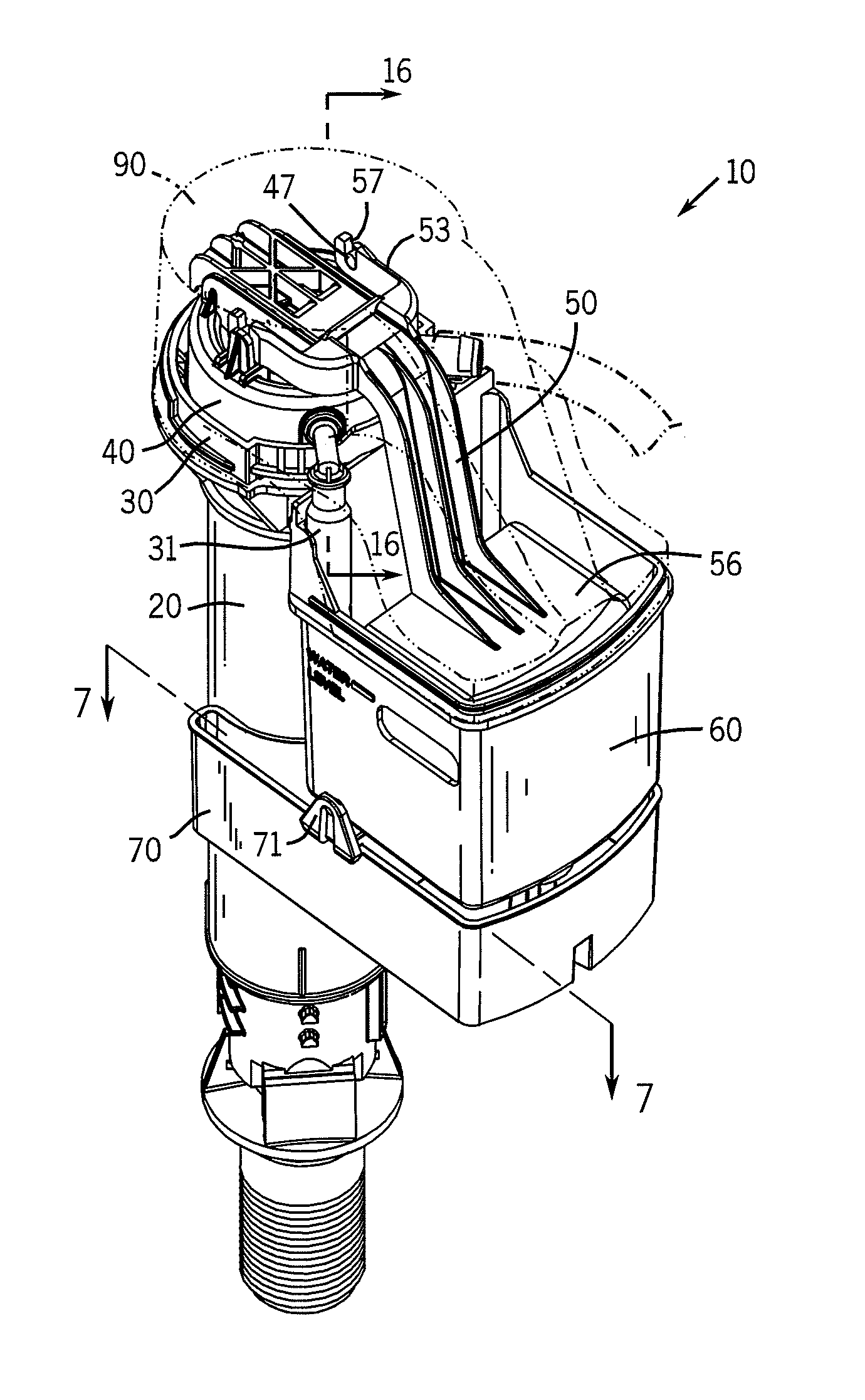
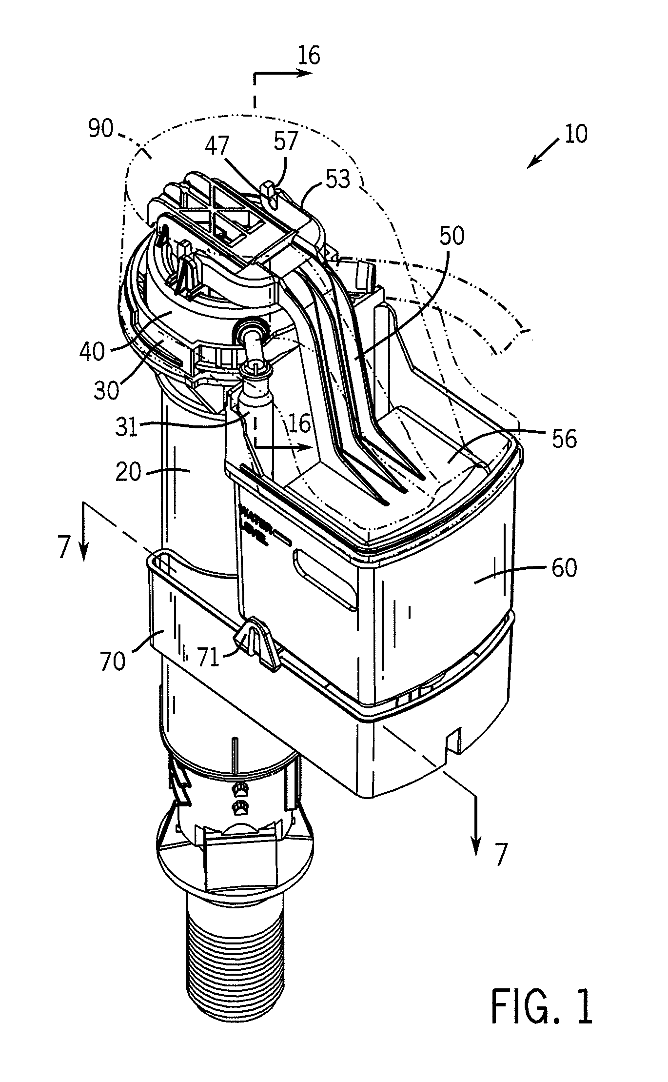
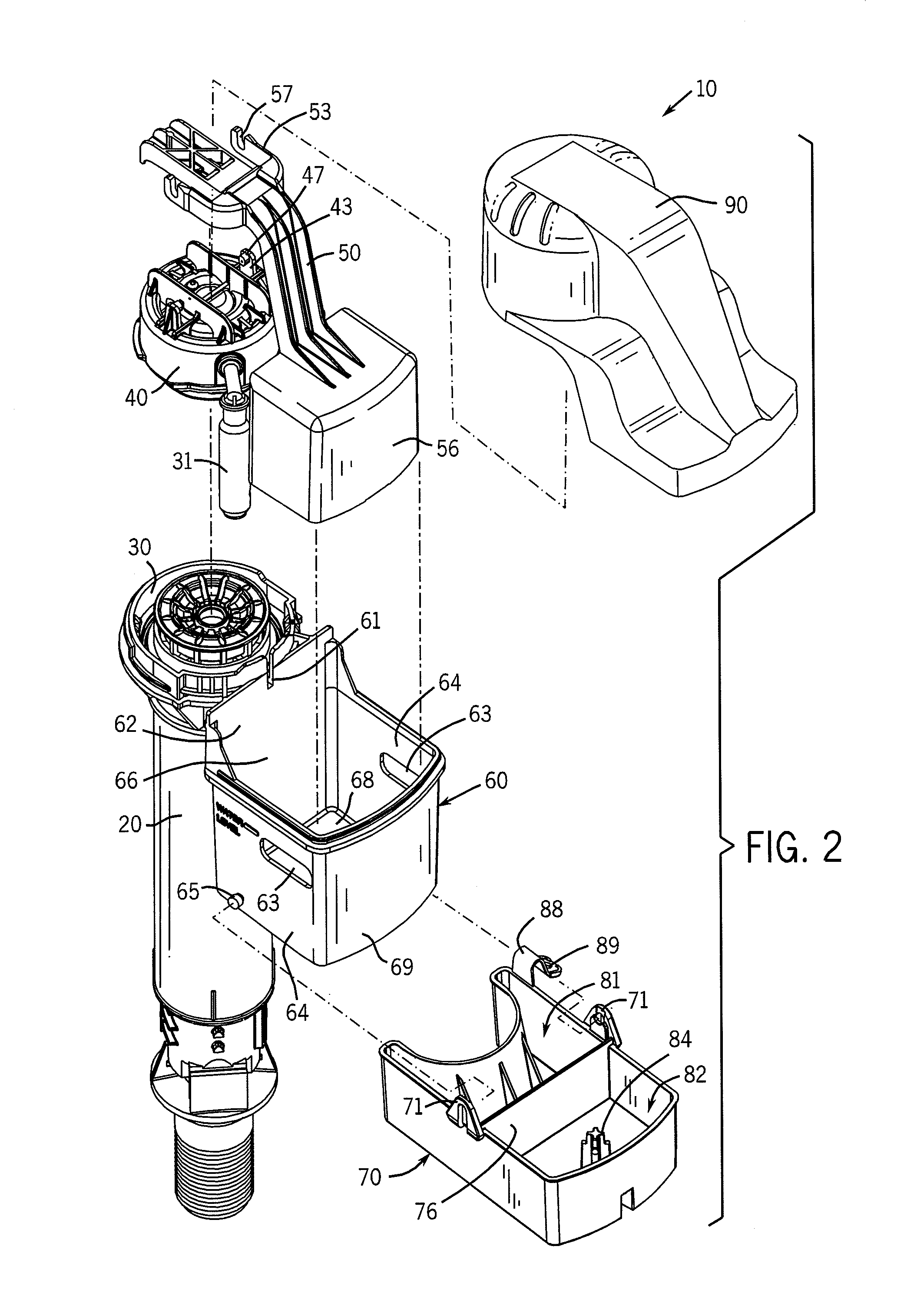
[0033]Referring now to the drawings in detail, wherein like-numbered elements refer to like elements throughout, FIGS. 1 and 2 illustrate a fill valve assembly and apparatus that is constructed in accordance with the preferred embodiment of the invention, the assembly and apparatus being designated generally by the numeral 10. For the most part, this assembly and apparatus 10 is constructed in accordance with the detailed description found in U.S. Pat. No. 7,661,438, issued Feb. 16, 2010, titled “Improved Water Saver Fill Valve and Assembly” (the '438 patent).

[0034]The overall fill valve assembly and apparatus 10 comprises an improvement over fill valves of the type generally disclosed and covered in U.S. Pat. No. 6,003,541 entitled “Unitary Float and Arm for Float Operated Valve,” U.S. Pat. No. 5,975,125 entitled “Combined Filter and Noise Suppressor for Fill Valve,” U.S. Pat. No. 5,836,346 entitled “Pilot Operated Diaphragm Fill Valve” and U.S. Pat. No. 5,715,859 entitled “Adjusta...


PUM


Abstract

An improved fill valve has a pivot valve body that is pivotally suspended immediately below a float housing and is movable between two positions. In a first position, the pivot valve body blocks the flow of water from the float housing. In a second position, the pivot body allows the flow of water from the float housing. The pivot valve body has two top compartments, each separated from the other by a wall. The first compartment retains an amount of water in it. The second compartment functions as a water flow restriction apparatus and includes an upwardly-extending member for sealing off a check valve that is disposed within the bottom of the float housing. A pressure compensating drip emitter allows water to trickle into the float housing at a very slow rate. The emitter comprises a labyrinth structure having a plurality of serpentine pathways formed in its outer surface.

Description

[0001]This application is a continuation in part of U.S. patent application Ser. No. 12 / 712,348 filed Feb. 25, 2010 which claims the benefit and priority of U.S. Provisional Patent Application No. 61 / 155,204 filed Feb. 25, 2009.FIELD OF THE INVENTION[0002]The present invention relates generally to plumbing fixtures and to the component parts that are used in them. More particularly, it relates to a fill valve and assembly for flush systems used in gravity flush toilets. It also relates to such a fill valve and assembly that prevents water wastage under conditions where the toilet tank is prevented from filling properly due to a catastrophic flush valve leak or tank leak. It also relates to such a fill valve and assembly that limits or reduces water leakage under conditions where a relatively small flush valve leak exists.BACKGROUND OF THE INVENTION[0003]Conventional toilets typically employ a generally rectangular porcelain tank mounted immediately above a porcelain bowl from which ...

Claims


Application Information

Patent Timeline
IPC IPC(8): F16K31/34
CPCF16K31/34F16K21/18F16K31/26E03D1/32Y10T137/7439
Inventor GUTHRIE, KEVIN J.
Owner LAVELLE IND
Why Eureka
Try Eureka